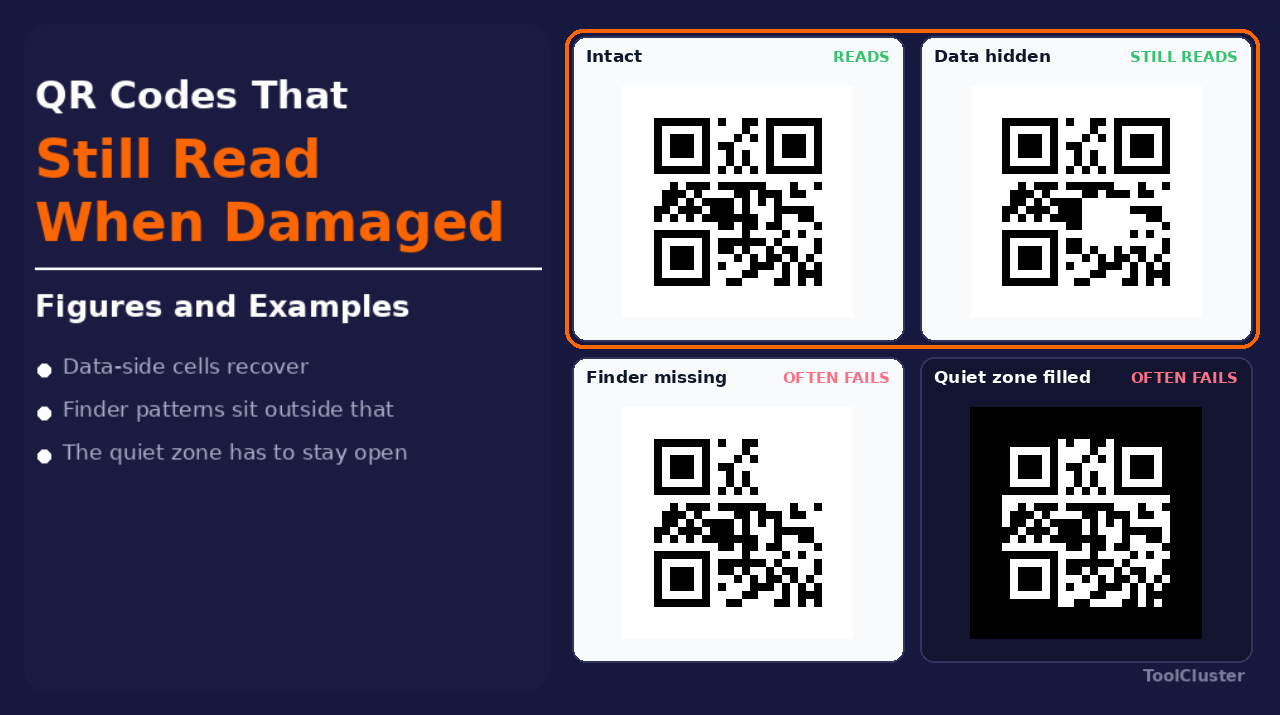
When you specify a QR code for a nameplate or a lot number, the questions to settle first are about use: in what environment will it be read, and how much damage is acceptable? The short answer is that a QR code keeps its data by recovering missing data cells through a method called error correction. It is not the finder patterns that do this, and it is not some process that redraws the damaged area from a blurry image.
Designing around this recovery is called damage-tolerance design. It also explains something many people have noticed with their phones: the camera only glances at a QR code, yet the URL inside it pops up anyway. This article walks through how that works, using real images and the simulator in QR for part marking.
Key points of this article
| Section | What to use in your design |
|---|---|
| How error correction works | Recovers data-side cells. Finder patterns are not covered |
| Acceptable damage range | Roughly 30% of the data side even at H. Position and role come before area |
| Module roles | Finder patterns, the cell grid (timing), level info (format), data and correction, quiet zone |
| Damage tests in the simulator | Comparison sheet with dust, oil film, chips and halation |
| Check with your phone whether reading changes when elements are missing | A real QR code. Data-side damage reads; finder and quiet zone often fail |
| Nameplate design values | Square modules, a high error correction level, quiet zone. Percentages are not a guarantee |
How error correction works
A reader decodes a QR code in two steps: the three finder patterns fix the code’s position and orientation, and only then are the data and correction cells read. Even if part of the data side is missing, the original content can be rebuilt from the correction cells that survive. Nothing is being redrawn from a blurry image.
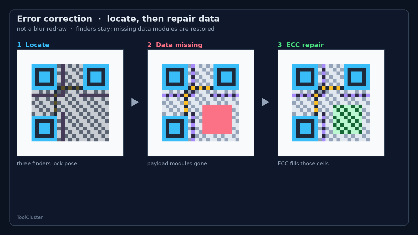
This repair comes in four levels, called L, M, Q and H, with usual guideline figures of about 7%, 15%, 25% and 30%. These numbers are a correction budget carried on the data side — not a licence to erase that share of the whole symbol. Even at H, losing half the code is beyond the budget. And when one finder pattern is badly damaged, the reader often cannot even judge the code, no matter how much of the data survives.
A logo in the centre is the same as deliberately damaging the data side. Its area eats into the correction budget. On a nameplate, the shape of the cells and the margin around the code come before any logo.
Acceptable damage range
Damage is acceptable when the code can still be located and the data-side loss stays within the budget of the error correction level you chose. What must not be damaged: the finder patterns, the light margin around the code (the quiet zone) and, in some cases, the cells that record the error correction level. If the margin is filled by black or by light bouncing off metal, the code cannot be located even with all of its data intact.
The role of the damaged cells matters before any percentage of area. The same 20% can read when it lands on central data and fail when it takes out a corner finder pattern. When you probe this boundary with a production reader, use the same phone or handheld scanner as on the process line and keep the lighting unchanged — that keeps the later simulator runs comparable.
| Covered area | Side affected | Typical outcome |
|---|---|---|
| No damage | Baseline | Baseline read |
| One finder pattern | Locating | Often fails |
| Central data area | Data (error correction) | May stay within budget at H |
| Outer white margin | Locating | May fail to be judged |
This is not a pass/fail standard; it is a test for choosing design values. Screen brightness and hand shake will sway the results.
Do not take a successful read on a screen as the damage tolerance of marked metal. Blown-out glare on metal (halation) and oil never show up in a cover-it-with-your-finger test.
Module roles
Each individual cell that makes up a QR code is called a module. The figure below is a schematic of a small QR code (Version 1) with its modules coloured by role — not a real, scannable code. Blue is the finder patterns; yellow is the timing pattern that marks out the module grid; purple is the format information, which records the error correction level among other things; grey is data and correction; the white frame is the quiet zone.
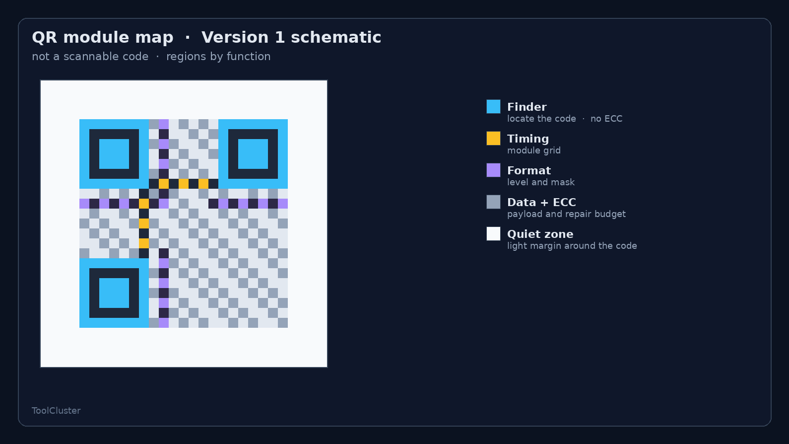
The error correction budget lives in the grey. Blue and white belong to locating and cannot be used to make up for damage after the fact. If the purple format modules are damaged, the error correction level itself may become unreadable. When you set acceptable damage, look at both the grey budget and whether blue and white survive.
Damage tests in the simulator
A fingertip makes clean, tidy damage. On a nameplate, damage is a pile-up of dust, oil film, scratches, jig edges and halation. The figure below shows the same schematic with the data side covered and with a finder pattern covered: on the left, damage that error correction may still absorb; on the right, damage that breaks locating.
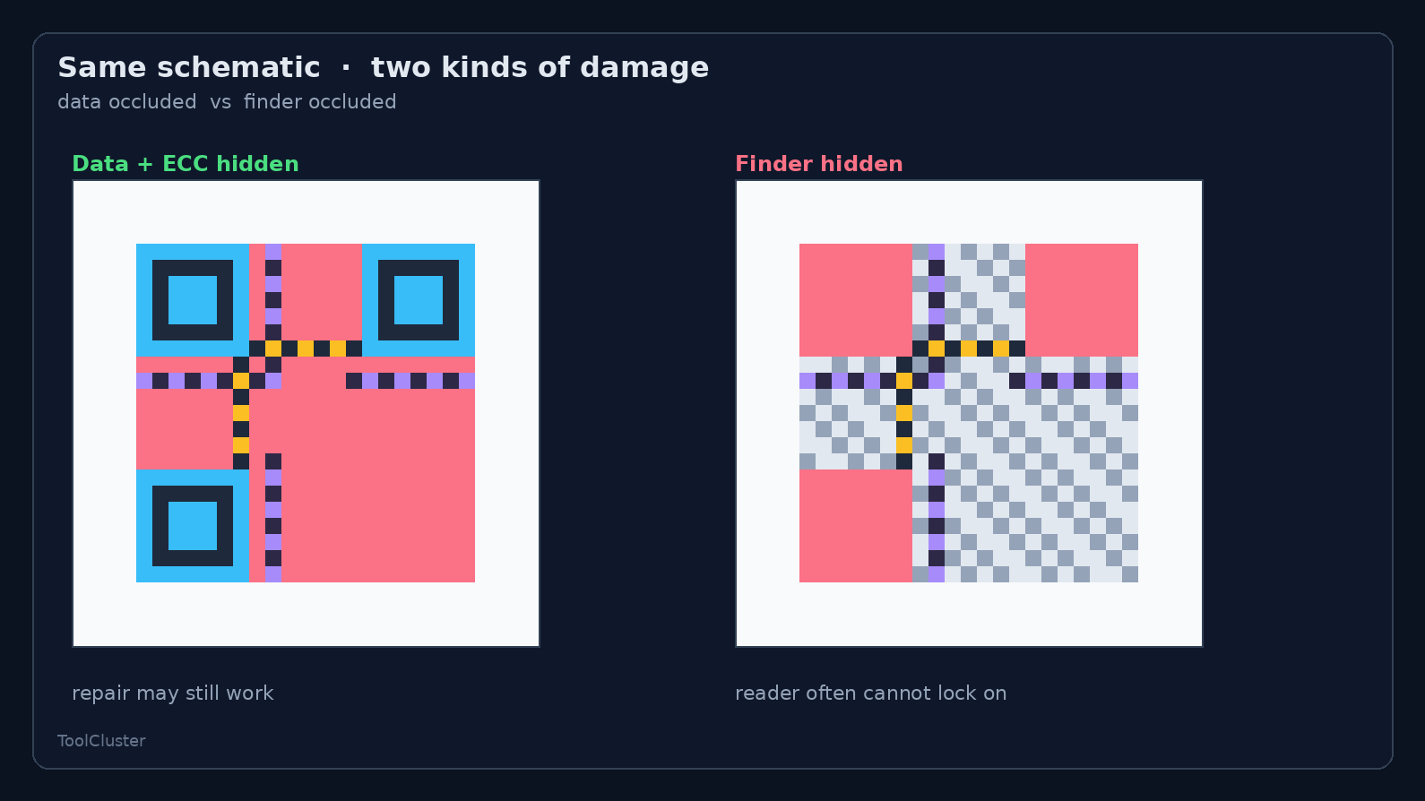
To bring dust and oil film into the design, open QR for part marking. Enter the lot number or URL, set the error correction level and the quiet zone first, then use the combined dirt-and-defect settings to stack dust, oil film, scratches, edge chips and halation. Read the comparison sheet or the test PNG with the same reader and similar lighting you used when probing acceptable damage. If a setting fails to read, widen the quiet zone or raise the error correction level before cutting metal.
The same smudge passes or fails depending on whether it lands on a finder pattern or on data. Move the overlay only after a failed read. The clean PNG and SVG go to marking; the test PNG exists to be read and to fail. The test overlays never go on the nameplate.
Read once with the initial placement and note which role failed before moving anything. If you move the overlay every time, you never pin down the boundary of acceptable damage.
Check with your phone whether reading changes when elements are missing
From here on we use a real QR code to confirm that reading depends on which required elements survive. The figures so far were role maps, not scannable module layouts. The figure below takes one code — error correction level H, lot number LOT-A17 — and applies the same damage as in the acceptable-damage table. Point your phone at the screen.
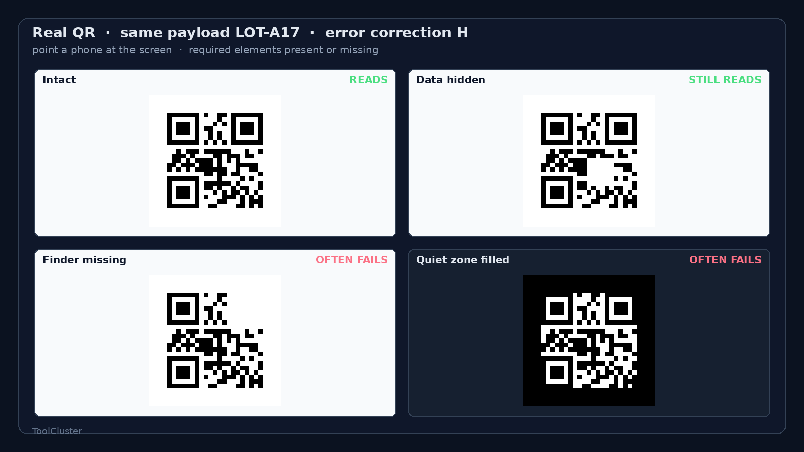
Top left is intact. Top right has only data-side modules removed: with the finder patterns and quiet zone in place, it can read as long as the loss stays within the error correction budget. Bottom left removes one finder pattern; bottom right fills the white quiet zone with black. When the locating side is damaged, the reader often cannot judge the code even though the data inside is untouched.
Screen brightness, zoom and phone model will sway the results. This is not a pass/fail standard but a test of which role’s loss kills the read. For dust and oil-film overlays, go back to the simulator in the previous section.
If the figure looks small, open the image before pointing your phone. A successful read shows LOT-A17.
Nameplate design values
An on-screen QR code can get by with error correction level L, even when small. A nameplate lives with oil mist, dust, jigs and the sheen of brushed metal, so the usual choice is square modules, a high error correction level and a quiet zone of at least 4 modules. On shiny metal it is common to try up to 8 modules.
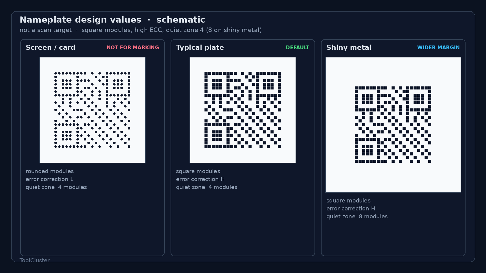
The left is screens and business cards: rounded or dotted modules can still read there. The centre is the typical plate: modules kept square, a high error correction level and a 4-module quiet zone. The right is for shiny metal: the same square modules with the quiet zone widened to 8. Halation pulls the dark modules and the white margin toward the same tone, and it is exactly this margin that it eats.
For laser or pin marking, keep the modules square so that a finder pattern still looks like a finder pattern after machining. Passing the simulator is no guarantee for your metal, your ink or your production reader; it is a rehearsal that weeds out bad settings before you cut.
Summary
A damaged QR code reads because of error correction. It covers the data-side modules only: even at level H the budget is roughly 30%, and the finder patterns and quiet zone sit outside it. Set acceptable damage by role, check pass/fail on a real code, then stack dust and oil film in QR for part marking to confirm. What goes to marking is the clean file.
Frequently asked questions
Q1. Can a half-missing code still read at error correction level H?
A. Half is beyond the budget of level H. The guideline is about 30% of the data side — not a share of the whole symbol you may erase. Part of the data side may still read; a finder pattern or the quiet zone will usually fail. Set your limit by covering parts while using the reader you actually deploy.
Q2. Are the error correction percentages of L, M, Q and H a guarantee?
A. The percentages are a guideline for the correction budget carried on the data side. Dirt position, deformed modules, lighting and reader differences make codes fail earlier than the numbers suggest. For nameplates, set a high error correction level and verify with the comparison sheet.
Q3. Does a logo in the centre stop the code from reading?
A. A centre logo is the same as deliberately damaging data-side modules. A small logo at error correction level H can still read. For lot marks on nameplates, put the quiet zone and contrast ahead of any logo.
Q4. If it reads on screen, will it read after marking?
A. A read on screen says nothing about the damage tolerance of marked metal. Metal reflections and ink bleed never appear with a finger and a screen. Test again under the process-line lighting, with the handheld scanner or phone you will actually use.
Q5. Can the dirtied test image be used for marking?
A. Keep the read-to-fail test separate from the file you hand over for marking. The test PNG contains the dirt overlays. What goes to the marking software is the clean PNG or SVG without overlays. The test picture never goes on a nameplate.
Q6. How much white margin does the code need around it?
A. When the white margin is filled by a jig, a print edge or blown-out glare on metal (halation), most readers cannot pick up the finder patterns. This margin is called the quiet zone. Four modules is the usual minimum, and on shiny nameplates it is common to widen it to 8.
Leave a Reply