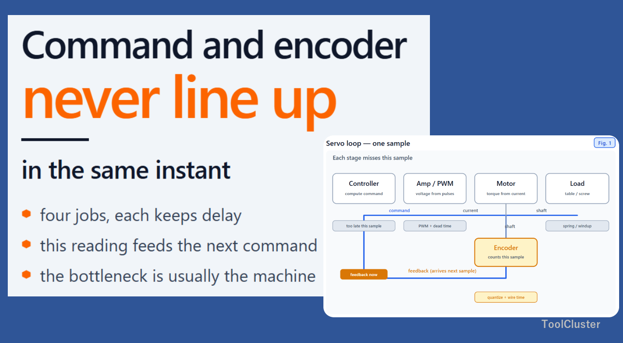
A servo is a device that moves a position to match a target. In one trip around its loop, the controller turns the target into a command, a box that converts power into current turns the motor, the shaft moves, and the value from a sensor measuring rotation or position comes back to the controller. That sensor is called an encoder. Yet even with the clocks aligned, the loop never lines up at a single instant.
The delay pools in the time computation takes, in the power switching, in mechanical flex, and in when the reading is taken. There is no circuit that forces everything onto the same instant; instead, the missing amount is added in advance before the next reading, which keeps the following error within specification. What proportional, integral, and derivative mean is handed off to PID control, and how the A and B phases are read to the encoder article. Here we look only at the delay around the loop and where it is compensated.
Key points of this article
| Section | What it explains |
|---|---|
| The four jobs of the servo loop | Computing the command, converting to power, motion, and the encoder return |
| The gap between command and encoder return | Sample timing, the one-cycle compute delay, PWM, quantization, and where you measure. The bottleneck is usually the machine |
| Feedforward and delay compensation | Close the current loop fast and first, and add the missing amount to the command in advance. Vibration at a fixed frequency is also suppressed |
| Semi-closed and full-closed measurement | Measure only the motor shaft, or close the loop on a load-side scale |
The four jobs of the servo loop
The full trip from controller to encoder return is called the servo loop. This section splits that loop into four jobs.
The first is computing the command. The controller decides the next command from the difference between the target and the value that came back. Taking values at a fixed interval is called sampling, and one round of it is a sample. The value read in this sample, however, usually makes it only into the next sample’s command. This delay — the time the computation itself takes — is called the one-cycle delay.
The second is converting the command into power. As a voltage number, the command cannot turn the motor. Chopping DC into fine on-off pulses to build an average voltage is the job called PWM, and the gap kept so the upper and lower switches never conduct at once is called dead time. Here too, there is a delay between the command going out and current actually flowing. How a motor is stopped, and regeneration, are a separate story from loop delay, covered in stopping a DC motor.
The third is moving. Current becomes torque, and the shaft and load move. But screws and couplings flex like springs, so the motor shaft position and the table position are not the same number at the same instant.
The fourth is returning the position. The encoder is what turns the shaft or table position into pulses or numbers and sends them back to the controller. The steps in those numbers are called quantization. With serial return, time on the wire is added as well. Gray code and how the A and B phases are read belong to the encoder article; here we only care about when the returned value arrives.
| Job | Who does it | What happens in this sample |
|---|---|---|
| Compute the command | Controller | The value read now goes into the next command |
| Convert to power | Amp | Current flows after PWM and dead time |
| Move | Motor and load | The load lags by the amount of flex |
| Return the position | Encoder | After quantization and transmission, it is read at the next sample |
The figure below shows these four jobs as one loop. In the figure, the command has left the amp and is heading for the motor, while the encoder return sits on the side that arrives at the next sample.
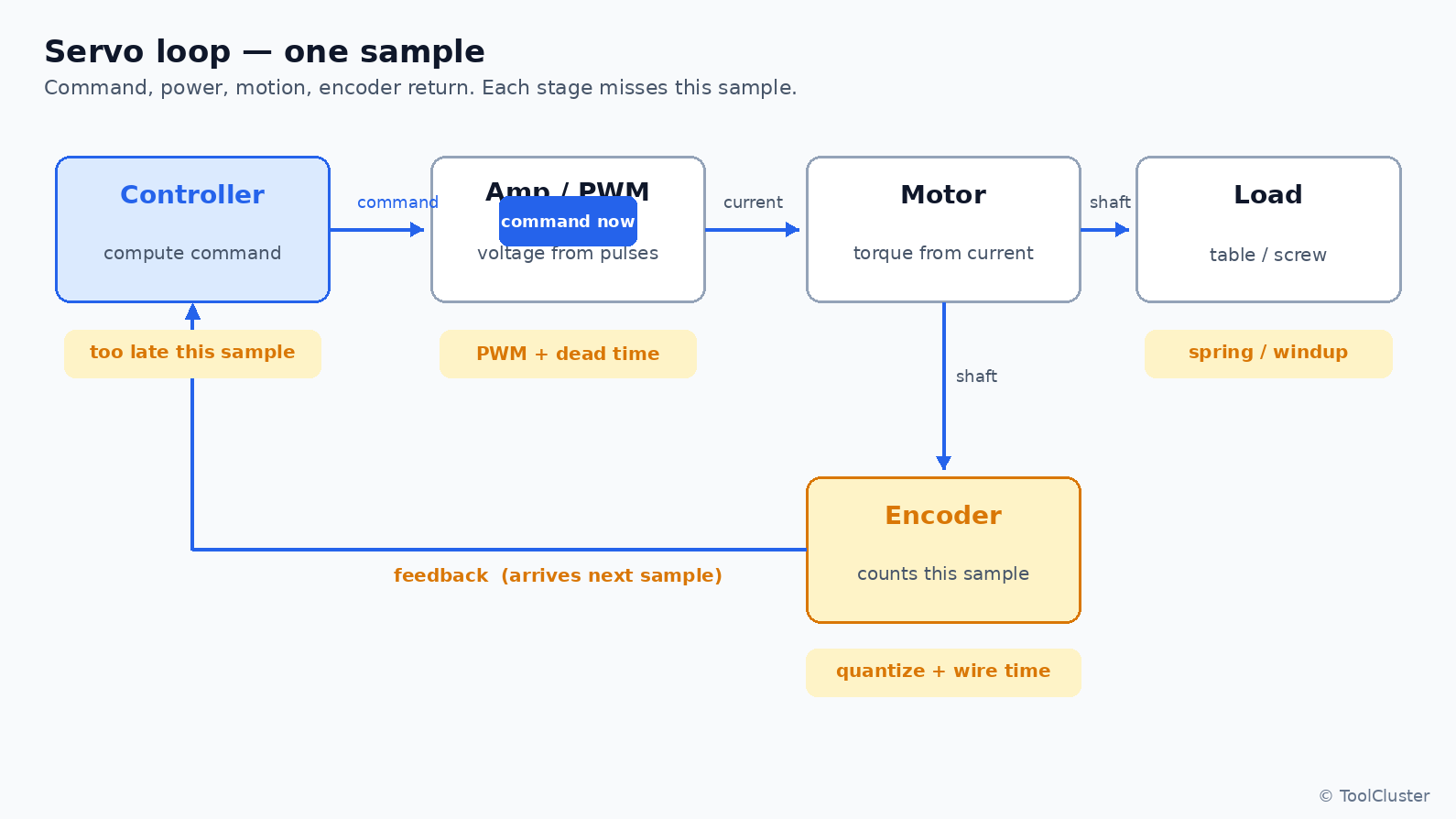
The short labels under each stage in the figure are the delays that pool there: at the controller, missing the current sample; at the amp, PWM and dead time; at the load, the screw’s spring; at the encoder, quantization and wire time. This is not, however, a matter of clocks being out of step.
Don’t decide the position will keep up just from the current-loop period on the datasheet. The current work finishes early, inside the amp, while the position sample time remains outside it.
The gap between command and encoder return
Let’s lay out the delays from the loop figure by where they pool. That they never fully align is not a fault: as long as the loop runs on discrete samples, the value at this instant can only feed the next command.
| Factor | Where it pools | Typical size in the field |
|---|---|---|
| Discrete sampling | Controller | Always present, and never goes away |
| One-cycle compute delay | Controller | The position period is longer than the current period |
| PWM and dead time | Amp | Usually small |
| Quantization and transmission | Encoder | Higher resolution does not remove the timing |
| Flex and where you measure | Machine | In precision work, this is often the bottleneck |
| 1 | In most plants, the bottleneck is the machine and where you measure. The motor-shaft encoder and the table position are not the same thing. Because of that, the spring of screw and coupling, backlash, and table flex stay larger than the electrical loop. Adding digits of resolution does not remove a spring you are not measuring. |
|---|---|
| 2 | The one-cycle compute delay cannot be removed, only hidden. The position read in this sample can only feed the next command. Even with a faster current loop, if the position is read slowly, the position delay remains. The loops are nested, though, so nothing is broken. |
| 3 | PWM, dead time, quantization, and serial transmission exist, but are usually small. This is where the amp and encoder catalog numbers matter. Still, they are less often the main reason a precision positioning spec is missed than the machine side. |
The current loop closes first, speed closes outside it, and position outside that. This is a nest in which fast loops support slow loops from the inside. The differing periods are therefore not a mix-up but a division of roles.
Assuming that raising the encoder resolution will make command and feedback align at the same instant. The quantization steps do get finer. But the sample timing and the unmeasured spring remain. So before adding digits, look at where you are measuring.
Feedforward and delay compensation
What compensates the delay is not a circuit that aligns everything at one instant. It is a mechanism that adds the missing amount in advance for the next sample, absorbing the following error within the specification.
First, the current loop is made fast and closed first. The position loop, outside it, issues commands at a longer interval. Because the current work is already done, by the time the position command arrives, the amp is close to ready to deliver torque. A faster current period still does not make the position fully catch up. The point is not catching up — it is finishing the inside first.
Next, the missing amount is added to the command in advance, from the target speed and acceleration. Rather than waiting for the feedback error, the side that already knows how far to move next does the adding. This is called feedforward. It is not a replacement for closing the error with proportional, integral, and derivative action; it fills the known delay before that work starts. What P, I, and D mean, and why steady-state error remains, is in the PID control article.
When the machine vibrates at a fixed frequency, a filter is inserted that suppresses just that frequency. This is called a notch. It does not remove loop delay; its job is to keep resonance from amplifying the command.
| Compensation | What it does | What remains |
|---|---|---|
| Close current first | Puts the fast loop on the inside | The position sample time |
| Feedforward | Adds the next move to the command in advance | The unmeasured spring |
| Notch | Suppresses vibration at a fixed frequency | The sample itself |
Clock alignment, so that multiple axes accept commands stamped with the same instant, is not about removing loop delay. That is timekeeping on the bus, and the distributed clocks of industrial Ethernet do that job. The stage where the command reaches the drive is in the EtherCAT section of industrial communication. The subject of this article is one loop on a single axis.
Making feedforward stronger does not fill in the spring at a place you are not measuring. As long as only the motor-shaft return is watched, the table-side lag gets added into the command as if it did not exist. Changing where you measure is the next section.
Semi-closed and full-closed measurement
In precision positioning, the trick that matters most is not more digits of gain but where you measure to close the loop.
Measure only the motor shaft, and the screw’s spring stays in the error. The load then lags the command — yet the controller believes the motor shaft is on target. This way of measuring is called a semi-closed loop. Put a scale on the table side instead and close the loop on the load position, and you have a full-closed loop. With the same command, how the load position lags changes.
In the figure below, the left side reads only the motor shaft, and the right side reads a table-side scale. The screw spring is there in both. What differs is where the feedback comes from.
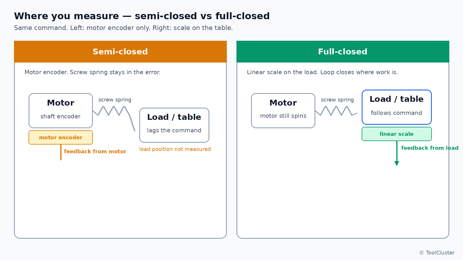
On the left of the figure, the feedback comes out of the motor, while the table lags the command and goes unmeasured. On the right, the feedback comes from the table-side scale. The screw’s spring remains, but the loop closes on the load position. There are also implementations that close motor-shaft speed and load position together, as a double loop. Before the names, though, look at whether the return comes from the motor or from the load.
There is a technique that divides the two sine phases finely to gain resolution, called interpolation. The quantization steps get finer as a result. But the sample timing remains, so interpolation is a matter of digits — it is no substitute for where you measure.
Scales and screws both grow with temperature. Heat, however, is a separate error from the loop delay, so one sentence is all it gets here. The heart of compensation stays where it was: measure in the right place, and add the missing amount in advance.
Assuming that the moment you go full-closed, you can keep raising the gains as if still semi-closed. Closing on the load side puts the screw’s spring inside the loop, which changes how stability is achieved. So when you change where you measure, revisit how the inner current and speed loops are closed as well.
Summary
One servo loop is command computation, power conversion, motion, and encoder return — and it never aligns at a single instant. The delay pools in the sample timing, the compute cycle, PWM, quantization, and mechanical flex, and in most plants the bottleneck is the machine and where you measure. What compensates is not perfect synchronization but closing current first, adding the missing amount in advance, and closing the loop on the load side. The goal is to absorb the following error within the specification.
The A and B phases and Gray code continue in encoders, and proportional, integral, and derivative in PID control. Robot joint servos run this same loop, too.
Frequently asked questions
Q1. Does a faster current-loop period make the position fully catch up?
A. No. A faster current-closing period lets torque come out sooner. But the sample timing for reading the position remains. The inside is being finished first; the position loop’s cycle is not being removed.
Q2. Does higher encoder resolution remove the delay?
A. No. The quantization steps do get finer. But the sample timing and the unmeasured spring remain. So before adding digits, check whether the feedback comes from the motor shaft or from the load.
Q3. What is the difference between semi-closed and full-closed?
A. Where you measure. Semi-closed closes the loop with the motor-shaft encoder alone, so the screw’s spring stays in the error. Full-closed closes on the load position, such as a table-side scale. The spring remains, but the loop closes where the work is being done.
Q4. Is feedforward a replacement for PID?
A. No. Feedforward adds the next move to the command in advance, while proportional, integral, and derivative still close the error. And adding in advance does not fill the spring at a place you are not measuring.
Q5. Do robot joints run the same loop?
A. Yes. A joint servo is also command, power, motion, and encoder return. This is not about a cell PLC feeding the trajectory every cycle; the loop delay and where you measure are the same for an arm as for a table.
Leave a Reply