Equipment does not run only under the conditions printed on its nameplate. The supply voltage can leave its nominal value for short periods, an earthquake accelerates the floor, wind pressure acts on outdoor surfaces, and snow load acts on roofs. On the equipment side, each of these external conditions turns into a different physical quantity: a voltage deviation becomes the time a power supply can hold its output and the torque a motor can deliver, acceleration becomes anchor load, wind speed becomes face pressure, and snow depth becomes load.
What matters, then, is not the name of the disaster but which quantity acts on what. This article starts with the power supply and the service entrance that every plant has, and then covers earthquakes, typhoons, and snow, focusing on the phenomena and their consequences.
Key points of this article
| Section | What this section explains |
|---|---|
| Voltage Deviation and Equipment Tolerance | In the same sag, the 24 V supply, motors, welders, and HVAC stop in different ways |
| Receiving Class and Plant-Side Risk | In the United States, Europe, Japan, and Brazil, the same load changes where the voltage drops and how far an outage spreads |
| Seismic Acceleration and Anchor Load | Turning intensity guide values into horizontal force; acceleration pulls on the anchors |
| Typhoon Wind Speed and Wind Pressure | Converting wind speed into wind load, using an outdoor cabinet as the example |
| Snow Depth and Snow Load | Converting depth into a downward load, using a canopy roof as the example |
Voltage Deviation and Equipment Tolerance
Even when a control panel’s nameplate says 200 V, the actual voltage can drift from nominal. A short drop is called a voltage sag, a short interruption a momentary outage, and a short rise a momentary swell. How often they occur depends on the region and the grid. On the equipment side, the first thing to check is which voltage the deviation applies to: the AC input, the 24 V control supply, or the motor terminals.
While checking, keep in mind that the “±10%” on a nameplate does not mean the site voltage always stays inside that range. The tolerance range, the manufacturer’s guaranteed range, and the design margin are three different numbers. Likewise, the same ±10% refers to different voltages at the 200 V AC input, on the 24 V control supply, and at the motor terminals. So even while the AC input stays within tolerance, the PLC stops once the regulated power supply runs out of the time it can hold its output voltage.
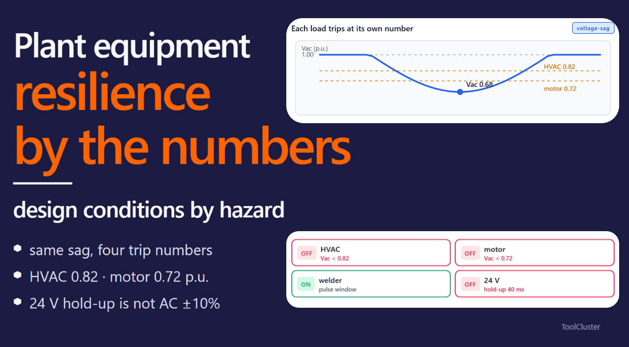
The same voltage deviation stops different equipment under different conditions. The 24 V control supply, motors, welders, and HVAC each watch a different voltage, and each affects the other equipment differently. The table below summarizes those differences.
| Equipment | Voltage that matters | What goes wrong first | Effect on other equipment |
|---|---|---|---|
| PLC / control (24 V) | The regulated supply’s output, and the time it can hold that output | The 24 V drops and the CPU, sensors, and fieldbus stop. Contactors often drop out before the PLC does | Small as a load |
| Motor | Terminal voltage; the DC bus for inverter drives | Torque is roughly proportional to the square of the voltage. At low voltage the current rises for the same load, leading to overheating or stalling | Starting current pulls down the surrounding voltage |
| Welder | Terminal voltage during the pulse | The arc becomes unstable. Inverter welders stop on DC-bus undervoltage | Often a main cause of sags inside the plant |
| HVAC | Compressor terminals and the contactor | A sag drops the contactor, and the restart pulls the voltage down again. If process HVAC stops, the process stops | Compressor starting causes sags |
A note on the PLC row: wide-range regulated supplies can accept AC inputs from 85 V to 264 V. That is why “the PLC will ride through ±10% on the AC side” mixes up the AC input with the 24 V output. Whether the PLC stays up is decided by how many milliseconds the 24 V output can be held. Welders and HVAC, on the other hand, are not only affected by voltage drops but are also causes of them. For inverters and servo drives, watch the DC-bus voltage, just as for motors.
The figure below shows, for one and the same voltage waveform, the specific number at which the HVAC, the motor, the welder, and the 24 V supply each stop.

After checking the AC input tolerance, check separately how long the 24 V can be held. If a contactor drops out first, the outputs are lost even while the PLC itself keeps running.
Reading the nameplate ±10% as one withstand figure shared by every device in the panel. Because each device watches a different voltage, some equipment rides through while other equipment stops.
Receiving Class and Plant-Side Risk
The voltage class at which a plant receives power changes two things: how far an outage spreads, and where in-plant loads pull the voltage down. The class names and the typical voltages differ by region, but the conversion used on the equipment side is the same everywhere: from the class to where the voltage drops and how far an outage reaches. Keep in mind that a class name is a voltage range, not a guarantee that equipment will keep running.
Before reading the table, two terms: a bus is a section where panels are connected at the same voltage, and the secondary side is the lower-voltage side of a transformer. The table below can be switched by region; the region opened first matches the language of this article.
The frequency is 60 Hz. Up to 600 V AC is usually called low voltage, above that and below 69 kV medium voltage, and 69 kV and above high voltage. In plants, low voltage is typically 480 V or 208 V, medium voltage 4.16 kV or 13.8 kV, and high voltage 69 kV or 138 kV. Whether the transformer sits on the utility side or on site is what changes the grid-side current and how far an outage spreads.
| Service | Typical voltage | Transformer location | What changes first on the equipment side |
|---|---|---|---|
| low voltage | 480 V or 208 V | On the utility pole, or a small on-site transformer | Voltage drop in plant wiring is large. Welding disturbances easily reach the neighboring 24 V and the grid. An outage covers everything sharing the transformer |
| medium voltage | 4.16 kV or 13.8 kV | On site | Grid-side current is small. Starting and welding on the transformer’s low-voltage side remain, though. If an in-plant fault cannot be cleared in-plant, the whole plant goes down |
| high voltage | 69 kV or 138 kV | On site (large plants) | Grid-side voltage disturbance is small. When service is lost, however, the affected area is wide and recovery often takes time |
Even for the same welding pulse, the receiving class changes where the large current flows. The next table is a rough guide for about 30 kW on 480 V three-phase; it is not a value for equipment selection.
| Service | Secondary-side current | Approx. grid-side current | Neighboring 24 V |
|---|---|---|---|
| low voltage | About 36 A | About 36 A (same as in-plant) | Prone to sag on a shared bus, and the disturbance also reaches the grid |
| medium voltage | About 36 A (secondary) | About 1.3 A (13.8 kV, three-phase) | Sags on the secondary bus, but the grid barely sees it |
| high voltage | About 36 A (secondary) | About 0.13 A (138 kV, three-phase) | Same as medium voltage on the secondary, but an outage covers a wide area |
Note: Grid-side currents are rough figures for about 30 kW carried three-phase at that voltage. Wiring resistance and transformer impedance are not included.
The frequency is 50 Hz. Up to 1,000 V AC is usually called low voltage, above 1 kV up to 36 kV medium voltage, and above that high voltage. In plants, low voltage is typically 400 V, medium voltage 10 kV or 20 kV, and high voltage 110 kV. Whether the transformer sits on the utility side or on site is what changes the grid-side current and how far an outage spreads.
| Service | Typical voltage | Transformer location | What changes first on the equipment side |
|---|---|---|---|
| low voltage | 400 V | On the utility pole, or a small on-site transformer | Voltage drop in plant wiring is large. Welding disturbances easily reach the neighboring 24 V and the grid. An outage covers everything sharing the transformer |
| medium voltage | 10 kV or 20 kV | On site | Grid-side current is small. Starting and welding on the transformer’s low-voltage side remain, though. If an in-plant fault cannot be cleared in-plant, the whole plant goes down |
| high voltage | 110 kV etc. | On site (large plants) | Grid-side voltage disturbance is small. When service is lost, however, the affected area is wide and recovery often takes time |
Even for the same welding pulse, the receiving class changes where the large current flows. The next table is a rough guide for about 30 kW on 400 V three-phase; it is not a value for equipment selection.
| Service | Secondary-side current | Approx. grid-side current | Neighboring 24 V |
|---|---|---|---|
| low voltage | About 43 A | About 43 A (same as in-plant) | Prone to sag on a shared bus, and the disturbance also reaches the grid |
| medium voltage | About 43 A (secondary) | About 0.9 A (20 kV, three-phase) | Sags on the secondary bus, but the grid barely sees it |
| high voltage | About 43 A (secondary) | About 0.16 A (110 kV, three-phase) | Same as medium voltage on the secondary, but an outage covers a wide area |
Note: Grid-side currents are rough figures for about 30 kW carried three-phase at that voltage. Wiring resistance and transformer impedance are not included.
The frequency is 50 Hz in eastern Japan and 60 Hz in western Japan. Up to 600 V AC is called low voltage, above 600 V up to 7,000 V high voltage, and above 7,000 V extra-high voltage. In plants, low-voltage service is typically 200 V or 400 V, high voltage 6.6 kV, and extra-high voltage 22 kV or 66 kV. Whether the transformer sits on the utility side or on site is what changes the grid-side current and how far an outage spreads.
| Service | Typical voltage | Transformer location | What changes first on the equipment side |
|---|---|---|---|
| Low voltage | 200 V or 400 V | Usually on the utility pole (utility-owned) | Voltage drop in plant wiring is large. Welding disturbances easily reach the neighboring 24 V and the grid. An outage covers everything sharing the transformer |
| High voltage | 6.6 kV | On site | Grid-side current is small. Starting and welding on the transformer’s low-voltage side remain, though. If an in-plant fault cannot be cleared in-plant, the whole plant goes down |
| Extra-high voltage | 22 kV, 66 kV, etc. | On site (large plants) | Grid-side voltage disturbance is small. When service is lost, however, the affected area is wide and recovery often takes time |
Even for the same welding pulse, the receiving class changes where the large current flows. The next table is a rough guide for a 200 V, 150 A pulse (about 30 kW); it is not a value for equipment selection.
| Service | Secondary-side current | Approx. grid-side current | Neighboring 24 V |
|---|---|---|---|
| Low voltage | 150 A | 150 A (same as in-plant) | Prone to sag on a shared bus, and the disturbance also reaches the grid |
| High voltage | 150 A (secondary) | About 3 A (6.6 kV, three-phase) | Sags on the secondary bus, but the grid barely sees it |
| Extra-high voltage | 150 A (secondary) | About 0.3 A (66 kV, three-phase) | Same as high voltage on the secondary, but an outage covers a wide area |
Note: Grid-side currents are rough figures for about 30 kW carried three-phase at that voltage. Wiring resistance and transformer impedance are not included.
The frequency is 60 Hz, the same as in the United States. Low voltage is 220/380 V in some regions and 127/220 V in others. Medium voltage is typically 13.8 kV or 23 kV, and high voltage 69 kV or 138 kV; the class names follow IEC usage, close to Europe. Whether the transformer sits on the utility side or on site is what changes the grid-side current and how far an outage spreads.
| Service | Typical voltage | Transformer location | What changes first on the equipment side |
|---|---|---|---|
| Low voltage | 220/380 V or 127/220 V | On the utility pole, or a small on-site transformer | Voltage drop in plant wiring is large. Welding disturbances easily reach the neighboring 24 V and the grid. An outage covers everything sharing the transformer |
| Medium voltage | 13.8 kV or 23 kV | On site | Grid-side current is small. Starting and welding on the transformer’s low-voltage side remain, though. If an in-plant fault cannot be cleared in-plant, the whole plant goes down |
| High voltage | 69 kV or 138 kV | On site (large plants) | Grid-side voltage disturbance is small. When service is lost, however, the affected area is wide and recovery often takes time |
Even for the same welding pulse, the receiving class changes where the large current flows. The next table is a rough guide for about 30 kW on 380 V three-phase; it is not a value for equipment selection.
| Service | Secondary-side current | Approx. grid-side current | Neighboring 24 V |
|---|---|---|---|
| Low voltage | About 46 A | About 46 A (same as in-plant) | Prone to sag on a shared bus, and the disturbance also reaches the grid |
| Medium voltage | About 46 A (secondary) | About 1.3 A (13.8 kV, three-phase) | Sags on the secondary bus, but the grid barely sees it |
| High voltage | About 46 A (secondary) | About 0.13 A (138 kV, three-phase) | Same as medium voltage on the secondary, but an outage covers a wide area |
Note: Grid-side currents are rough figures for about 30 kW carried three-phase at that voltage. Wiring resistance and transformer impedance are not included. For Portugal (50 Hz, 400 V), see the Europe table.
In every region, raising the receiving class makes the grid-side current smaller. Welding and motor starting on the transformer’s secondary side, however, remain.
The figure below shows that even though the class names differ by region, the mechanism is the same. From top to bottom: at utilization voltage the sag reaches the grid; with an on-site transformer the grid current is small; at the highest class an outage spans a wide area. And the 24 V sags at every class.

By contrast, with a single incoming line, a fault on that line stops the whole plant. Even two lines can be lost together if they share a route. And if an in-plant fault cannot be cleared by an in-plant breaker, the upstream breaker opens first and the whole plant goes down. Installation procedures are outside this article’s scope.
Once the receiving class and the number of lines are set, the next step is protection and the placement of voltage-holding equipment (UPS). The capacity you need depends on whether you hold up only the 24 V or the entire process.
Raising the receiving class reduces the disturbance on the grid side. Treat the secondary-side 24 V and the welders as a separate condition that remains.
Assuming that raising the receiving class makes sags disappear. The grid-side current gets smaller, but starting and welding on the secondary side remain.
Seismic Acceleration and Anchor Load
When an earthquake accelerates the floor, the equipment’s mass does not follow instantly. Multiplying acceleration by mass gives a force, called the inertia force. With self-weight W, gravitational acceleration g, and horizontal acceleration a, the horizontal inertia force is F = (a/g) W. So 0.3 g means a horizontal force of 0.3 times the self-weight, and 1 g a force equal to it. That force pulls on the anchors and the base plate, or acts to lift the legs.
You cannot take that acceleration directly from a reported intensity. Magnitude describes the size of the source, whereas intensity describes the shaking at a given location. Japan uses the JMA seismic intensity scale, which runs from 0 to 7 with levels 5 and 6 each split into lower and upper. Abroad, shaking is often reported on the Modified Mercalli Intensity scale (MMI). Equipment calculations, however, use horizontal acceleration in g. It is not unusual for a nearby magnitude-5 earthquake to produce a larger site acceleration than a distant magnitude 7.
The table below is a rough guide for the case where the horizontal acceleration acts unreduced on a mass fixed to the floor. JMA intensity is not determined by peak acceleration alone, so within one level the acceleration varies from site to site. These are therefore not values for equipment selection.
| Case | Modified Mercalli | JMA intensity | Example horizontal acceleration | Multiple of self-weight |
|---|---|---|---|---|
| Most people are startled | V–VI | 4 | 0.03–0.08 g | 0.03–0.08 times |
| Furniture can topple | VII | 5 Upper | 0.15–0.25 g | 0.15–0.25 times |
| Hard to remain standing | VIII | 6 Lower | 0.25–0.3 g | 0.25–0.3 times |
| Most unsecured furniture topples | IX | 6 Upper | 0.3–0.4 g | 0.3–0.4 times |
Note: The Modified Mercalli Intensity scale (MMI) is the shaking scale used in the United States and elsewhere. JMA intensity is the scale used by the Japan Meteorological Agency. The correspondence in this table is approximate.
For example, a cabinet with a mass of 1 tonne sees, at the intensity 6 Lower guide value (about 0.3 g), a horizontal force of about 3 kN (roughly 300 kg-equivalent). On upper floors or on low-stiffness platforms, the acceleration can exceed the ground-level value. On top of that, a high center of gravity raises the tension-side anchor load further at the same acceleration.
On the installation side, pre-tensioning the bolts lets the joint faces carry most of the load fluctuation in compression.
The figure below shows the relationship: the larger the acceleration, the larger the load on the tension-side anchors. Anchor sizing is not covered.

Selecting anchors from the intensity level alone. Within one level, the acceleration waveform, the mass, and the height of the center of gravity all change the anchor load.
Typhoon Wind Speed and Wind Pressure
What acts on outdoor cabinets, platforms, and conveyor covers is not the wind speed itself but the pressure on their faces. Pressure is roughly proportional to the square of the wind speed, so doubling the speed roughly quadruples the load on a face. A storm-track map is no substitute for that pressure.
As an example, take an outdoor cabinet 0.8 m wide and 2.0 m tall; the wind-facing area is 1.6 m². The velocity pressure q — the pressure computed from wind speed — is 0.6 v² (in N/m², with v in m/s) for an air density of about 1.2 kg/m³. The horizontal wind load is this velocity pressure times the area, with a force coefficient of 1: a rough guide, not a value for equipment selection.
| Case | Wind speed | Velocity pressure | Horizontal wind load |
|---|---|---|---|
| Around the typhoon threshold | 18 m/s | About 190 N/m² | About 0.3 kN (roughly 30 kg-equivalent) |
| Storm-force zone | 25 m/s | About 380 N/m² | About 0.6 kN (roughly 60 kg-equivalent) |
| Double the speed (four times the pressure) | 36 m/s | About 780 N/m² | About 1.2 kN (roughly 130 kg-equivalent) |
| Strong typhoon | 40 m/s | About 960 N/m² | About 1.5 kN (roughly 160 kg-equivalent) |
Note: Force coefficient 1; no increase for height above ground is included. 1 kN is roughly a 100 kg-equivalent force. The typhoon threshold follows the JMA definition (maximum winds of roughly 17 m/s or more), the storm-force zone means average winds of 25 m/s or more, and a strong typhoon means maximum winds of 33 m/s or more and less than 44 m/s.
For this cabinet, a strong typhoon (40 m/s) applies a horizontal force of about 1.5 kN (roughly 160 kg-equivalent). Height, gusts, and a different force coefficient change the value even at the same wind speed.
The figure below shows the pressure on the cabinet face and the horizontal force growing as the wind speed rises; the current wind speed, velocity pressure, and horizontal force (kN and kg-equivalent) update as numbers. It also shows where the current speed falls in the JMA typhoon categories and on the hurricane scale (SSHWS). JMA uses 10-minute averages and the hurricane scale 1-minute averages, so the categories do not line up at the same wind speed. Enclosure ratings differ by device, so neither the table nor the figure can stand in for an allowable value.

Snow Depth and Snow Load
Never size a roof load from snow depth alone. Snow gains weight by absorbing rain, and with changing weather it can melt and densify before fresh snow lands on top, ending up heavier than it looks. Skylights and support frames can also run out of capacity under a local pile-up before the roof’s average load becomes critical. Snow, moreover, is a condition with strong regional differences.
As an example, take a 2.0 m × 2.0 m outdoor canopy roof; the area is 4.0 m². Fix the unit snow load at the value commonly used with Japan’s Building Standard Act: 20 N/m² per centimeter of depth, that is, 2 kN/m³. The snow load is the vertical force per unit area, and the whole-roof load is that value times the area. Both are rough guides, not values for equipment selection.
| Case | Snow depth | Snow load | Whole-roof load |
|---|---|---|---|
| 30 cm of snow | 0.3 m | 0.6 kN/m² | About 2.4 kN (roughly 240 kg-equivalent) |
| 60 cm of snow | 0.6 m | 1.2 kN/m² | About 4.8 kN (roughly 490 kg-equivalent) |
| 1 m, common in heavy-snow regions | 1.0 m | 2.0 kN/m² | About 8 kN (roughly 800 kg-equivalent) |
| The same 1 m, water-soaked | 1.0 m | 4.0 kN/m² | About 16 kN (roughly 1,600 kg-equivalent) |
Note: The unit load is 20 N/m² per centimeter of depth (2 kN/m³). Only the last row doubles the unit load, as a guide for water-soaked snow. 1 kN is roughly a 100 kg-equivalent force.
For this 2 m square roof, 1 m of snow applies a downward force of about 8 kN (roughly 800 kg-equivalent). The last row shows that at the same depth, water-soaked snow weighs more.
The figure below shows the post load growing as the depth grows — and then, when rain falls on the standing snow, the density rising and the post force growing further at the same depth. Member sizing is not covered.

Summary
For voltage, separate the places you look at — the AC input, the 24 V control supply — and check the deviation and the hold-up time for each. The receiving arrangement, whatever the class is called in your region, sets where the voltage drops and how far an outage spreads. In an earthquake, acceleration becomes anchor load; in wind, speed becomes face pressure; in snow, depth becomes load. What design uses are the values after these conversions. Recommended plate thicknesses or anchor sizes, and judgments based only on where events have happened before, are outside this article.
Frequently asked questions
Q1. Will a PLC ride through ±10% of rated voltage?
A. The nameplate range of the AC input and the time the 24 V output can be held are two different things. With a wide-range supply, the output side can therefore drop first while the AC input is still present. Contactors, in turn, can open even before that.
Q2. Does raising the receiving class eliminate sags?
A. The grid-side current becomes smaller, but starting and welding on the secondary side remain. At utilization voltage, on the other hand, the same pulse reaches the grid more easily.
Q3. Are intensity and acceleration the same thing?
A. No. Intensity is a scale for the shaking at a location, not a force. What acts on the anchors is acceleration times mass. And within one intensity level, the acceleration has a wide range.
Q4. If the wind speed doubles, what happens to the wind pressure?
A. The pressure on a face roughly quadruples, because pressure is proportional to the square of the wind speed. In the typhoon section’s table, 18 m/s and 36 m/s form this pair. For the 0.8 m wide, 2.0 m tall outdoor cabinet, that is roughly 30 kg-equivalent at 18 m/s and roughly 130 kg-equivalent at 36 m/s.
Q5. Once I know the snow depth, is the load determined?
A. Depth alone does not determine it; multiplying by the unit load turns it into a downward force. For the 2 m square roof, 1 m of snow is roughly 800 kg-equivalent, and the same 1 m of water-soaked snow roughly 1,600 kg-equivalent. Local pile-ups can also exceed a member’s capacity before the average load does.
Leave a Reply