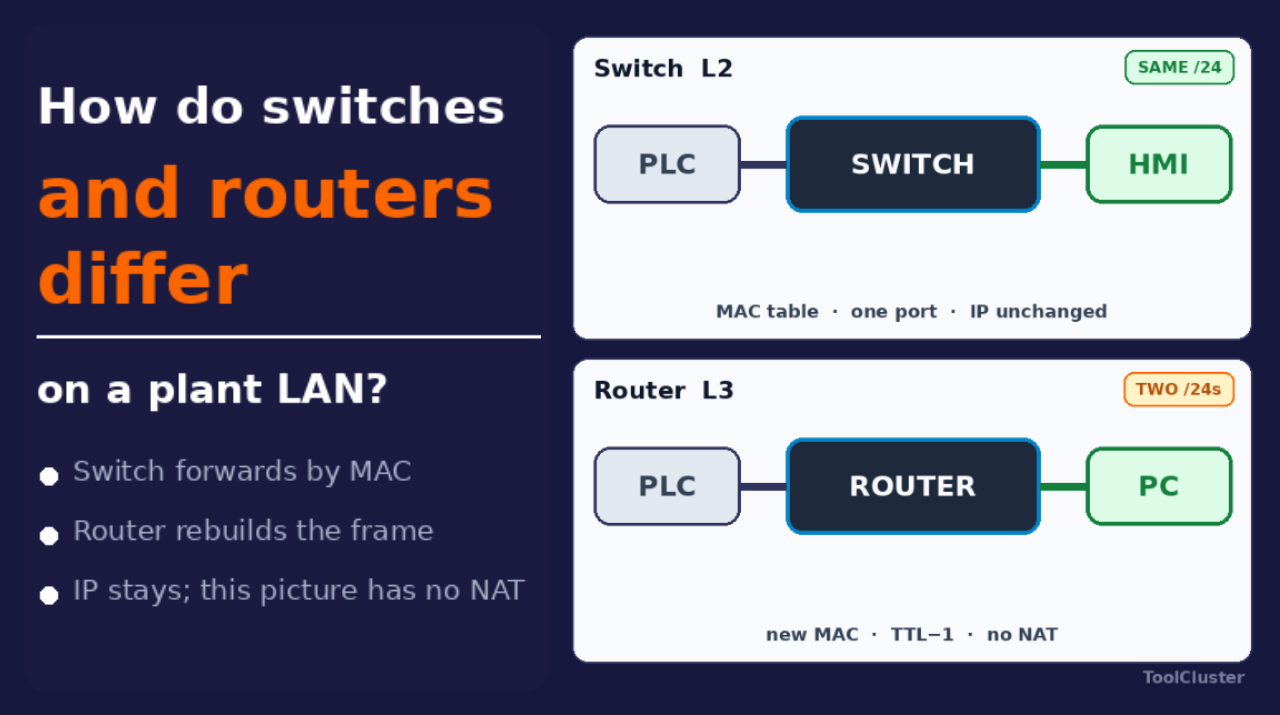
Inside control cabinets and in office racks alike, there are devices with bundles of cables plugged in, spreading the communication around. They are called “switches” and “routers”, but the real classification is how the box handles each chunk of data that arrives over a cable. In plant networking especially, mixing the two up can throw off the control cycle or let office-side broadcast traffic pour into the servo network — and that is real trouble.
Rather than the OSI chart from a textbook, this article separates two boxes as a matter of plant wiring: the box that sorts traffic by MAC within one subnet (the switch), and the box that reads the IP at the subnet boundary and rebuilds the frame (the router). It is a distinction that can be the root cause behind industrial communication problems and why office networks get slow. Along the way, the figure in the switch section shows a chunk of data crossing a switch, and the figure in the router section shows it being rebuilt by a router.
Key points of this article
| Section | What it covers |
|---|---|
| Same looks, different jobs | Classify not by the box’s name but by the destination it reads: MAC or IP |
| MAC forwarding in a switch | Within one subnet, it reads the MAC and picks a port. The IP is untouched |
| IP rebuilding in a router | At the subnet boundary, it strips the outer destination and rebuilds the delivery |
| What mixing them up causes | Nothing arrives, things lag, EtherCAT stops |
| VLANs and routes | One box can split broadcast domains. Delivering to another VLAN is the router’s job (or an L3 switch’s) |
| Switch vs. router at a glance | MAC vs. IP, broadcasts, EtherCAT, where the office PCs go |
Same looks, different jobs
The boxes look alike, so the label alone will not tell you what one does. In this section we classify them by the kind of destination they read.
Even the devices sold as “switches” range from small 8-port boxes with hardly any settings to industrial models with a design that keeps traffic flowing when a link breaks (called ring redundancy). The same name does not guarantee the same job inside.
The address each device carries is its MAC. The number that says which network, and which member of it, is the IP. The range treated as one network is a subnet, and writing its cut with a slash is CIDR — the /24 in 192.168.10.0/24. The same cut written out as 255.255.255.0 is the subnet mask. Counting the cut is covered in CIDR in the equipment LAN and in the CIDR visualizer. To see which IP your own device holds right now, use the IP check.
Forwarding by MAC within one subnet is called L2; reading the IP at the subnet boundary is called L3. The test is what the box looks at: only the destination MAC, or also the network part of the IP.
| Box | Reads | Reach |
|---|---|---|
| Switch | MAC | Within one subnet |
| Router | Network part of the IP | The subnet boundary |
| L3 switch | MAC and IP | L2 and L3 in one chassis |
Handing out addresses automatically is DHCP; swapping the address seen from outside is NAT. What offices call a “router” may be a home-style unit that bundles NAT, DHCP and wireless, or an L3 switch in the rack. The thread of this article stays the same: sort by MAC, or rebuild by IP. NAT comes up later in the router section.
Now for plant wiring. The plant’s controller is the PLC, input/output units placed at a distance are remote I/O, and the operator screen is the HMI. If the PLC, remote I/O and HMI only talk among themselves inside 192.168.10.0/24, an L2 switch is usually enough. The moment logs must go up to the office PCs’ network (a different subnet), or traffic must reach the internet, a router is needed at the boundary. Without one, the cable may be plugged in, but nothing arrives over IP.
MAC forwarding in a switch
This section covers what a switch does with each chunk of data. The chunk of data that travels inside a LAN cable is technically called an Ethernet frame. A frame entering a switch keeps its inner IP unchanged, as a rule. If the switch knows the destination MAC, it sends the frame out of that one port only.
The table that pairs each sender’s MAC with the port it came in on is the MAC table. A frame addressed to every device on the network at once — rather than to a single destination — is a broadcast, and the range a broadcast reaches is the broadcast domain. The protocol that asks around for a partner’s MAC is ARP. When the switch does not know the destination MAC, it floods the frame to the other ports in the broadcast domain — while memorizing the sender’s MAC in its MAC table, so there is less flooding next time. ARP, too, reaches everyone in the broadcast domain.
| Destination MAC | What the switch does |
|---|---|
| Known | Sends out of that one port only |
| Unknown | Floods beyond the incoming port |
| Broadcast | Reaches everyone in the domain |
| Sender | Gets memorized in the MAC table |
Why this matters on the plant floor: devices in the same subnet reach each other without passing a router. The PLC’s periodic read of its inputs and outputs is the scan. The PLC’s scan, the HMI’s screen refresh, and station-to-station traffic in EtherNet/IP or PROFINET (both industrial Ethernet standards) usually ride on this same L2.
The figure below shows the switch reading the destination MAC and sending out of one port only.
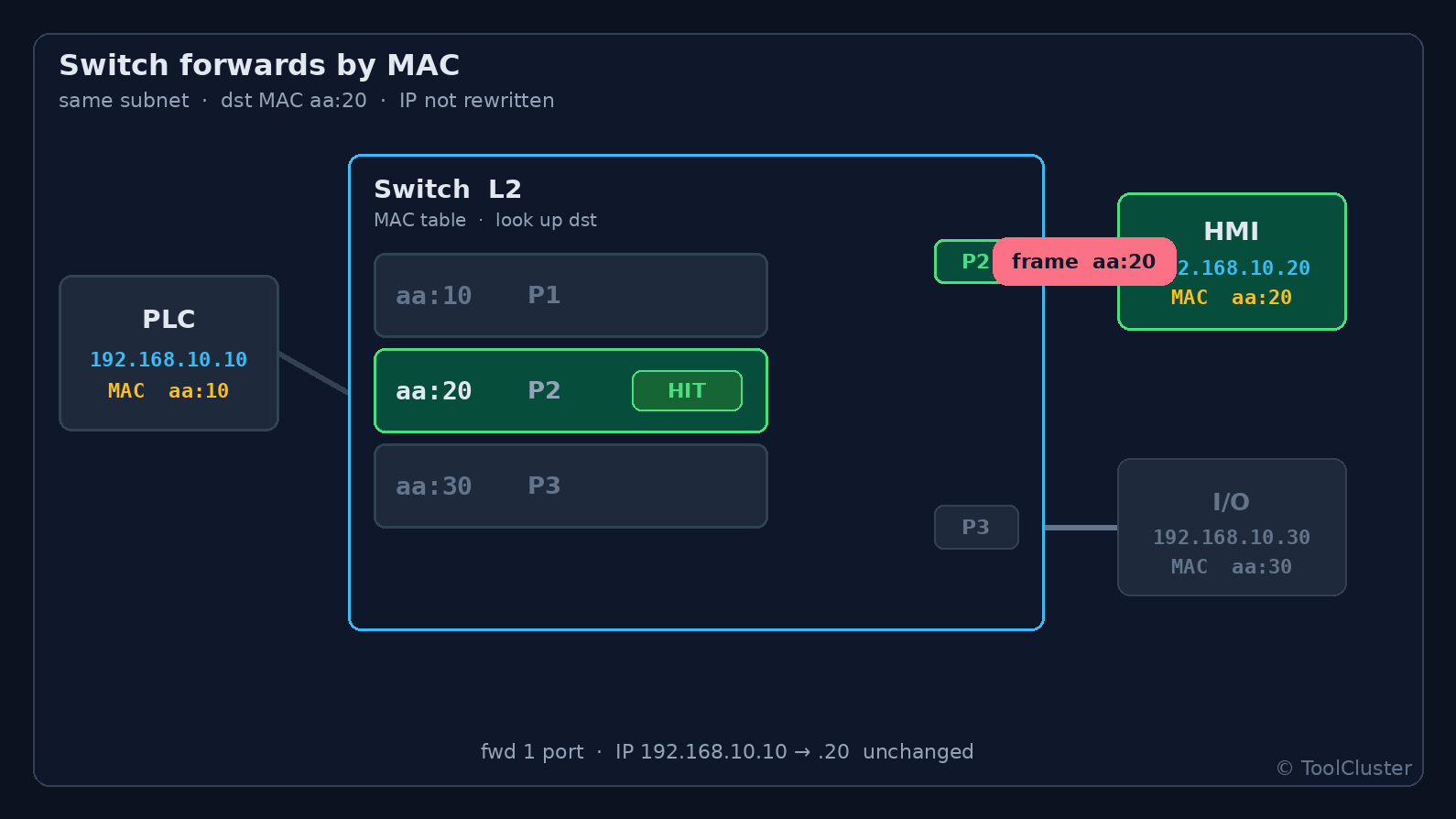
In the figure, the frame sits on the HMI-side port, and the inner IP has not been touched. The flood-to-other-ports behavior belongs to broadcasts.
A feature that lets chosen traffic go first is priority control; a feature that copies traffic to another port is mirroring. Drop a cheap office switch into a control cabinet as-is, and you may get a small MAC table and no priority control. The result: heavy broadcast traffic or mirroring load makes the cycle wobble. The slow office network is the office side of this story, but the failure pattern is the same — a broadcast domain that is too wide.
An EtherCAT slave is not the switch from the store shelf. Receiving a whole frame before sending it on is store-and-forward; reading and writing while the frame passes through is on the fly. A device that floods every received frame to all ports is a hub. EtherCAT works on the fly, not store-and-forward, and a hub in the chain breaks it. This pitfall is covered in the EtherCAT section of the industrial communication standards article. The “switch” in this article means a normal Ethernet switch.
IP rebuilding in a router
This section covers what a router does at the subnet boundary. The exit used to leave your own network is the default gateway, and in most cases that role belongs to a router. The cap on how many routers a packet may cross is the TTL. When the destination IP lies outside the subnet a device is on, the device first sends the packet to its default gateway. The router strips the outer destination (the MAC), lowers the TTL by 1, and rebuilds the chunk of data with the new MAC of the exit side. That is why, past a router, the MAC changes and the IP stays (unless NAT is involved).
The figure below shows the outer MAC being stripped and the frame rebuilt.
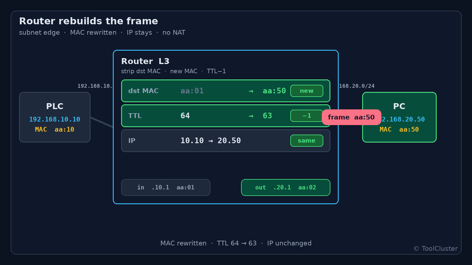
In the figure, the frame leaves with the new MAC of the exit side, and the inner IP is still there. NAT comes separately below.
The manufacturing execution system is the MES. In a plant, this boundary is typically where “control LAN” and “information LAN” part ways. Servo-cycle EtherCAT and the short PLC-to-PLC cycles stay on the control side; the MES and file shares go out past the router. The firewall is the box that decides, at that boundary, whether traffic may pass. Sometimes it shares the router’s chassis, sometimes it is a separate unit.
Once NAT is in play, the address seen from outside changes. Port forwarding and remote maintenance then become questions about the translation table, not the switch’s MAC table. NAT itself is beyond this article.
A switch with no settings to configure is an unmanaged switch.
Plugging the control devices and the office PCs all into one unmanaged switch with no router. ARP and Windows discovery packets then land in the same broadcast domain as the PLC. It runs for a while — until the week more PCs are added and the occasional lag begins. If you split, split the subnet, and put a router (or an L3 switch) at the boundary.
What mixing up switch and router causes
Here are the mix-ups from the opening, sorted into the three common cases.
| 1 | Using only a switch where a router is needed. A PLC on 192.168.10.0/24 and a line PC on 192.168.20.0/24 will not reach each other over IP without a default gateway, even with both cables in the same switch. The link lights come on. No traffic flows. |
|---|---|
| 2 | Putting a router where a switch would do. Sending traffic to remote I/O in the same subnet through a router adds ARP, TTL and NAT settings, and makes the latency of cyclic traffic hard to predict. For I/O on the floor, first check that it is reachable at L2. |
| 3 | Putting an Ethernet switch into an EtherCAT chain. The on-the-fly pass-through stops in a store-and-forward box. It looks like the same LAN; the job is different. |
Whether the PLC’s outputs are relay or transistor is one layer below all this (electricity inside the cabinet). What this article looks at is which boxes that PLC passes through to reach its partner.
VLANs and routes
This section covers how to split broadcast domains inside a single switch. As the switch section showed, devices plugged into the same box share a broadcast domain. Plug the control devices and the office PCs all into an unmanaged switch, and office-side broadcast traffic enters the servo network. The “real trouble” from the opening is this mixing.
In a plant you sometimes want control and office traffic on one switch, without adding another rack. One box, but separate broadcast domains — that is the requirement. A switch whose settings can be changed is a managed switch, and the managed-switch feature that splits broadcast domains is the VLAN. A VLAN’s job is to group the switch’s ports. It is not the router’s job (rebuilding delivery at the subnet boundary).
Here is a concrete setup. Take one 8-port managed switch. Ports 1–4 go to VLAN 10, connecting the PLC and the HMI on 192.168.10.0/24. Ports 5–8 go to VLAN 20, connecting the line PCs on 192.168.20.0/24.
| Ports | VLAN | Connected devices | Where broadcasts go |
|---|---|---|---|
| 1–4 | 10 | PLC / HMI | Only within VLAN 10 |
| 5–8 | 20 | Line PCs | Only within VLAN 20 |
Inside VLAN 10, the switch behaves as before: it reads the MAC and picks a port, without touching the IP. Windows discovery packets in VLAN 20 do not reach the PLC in VLAN 10. Same chassis, but the broadcasts no longer mix. That is the whole of the VLAN’s job.
The VLAN number and the subnet number are different things. VLAN 10 is a number the switch attaches to a broadcast domain; 192.168.10.0/24 is a cut in the IP space. The two are often aligned, but aligning them does not create a router. If the PLC on port 1 must send logs to the line PC on port 6, a VLAN alone will not deliver — a default gateway (a router, or an L3 switch) is needed. Same as mix-up 1: one box for the cables, but with different IP networks, MAC will not carry it across.
| Item | VLAN | Router (L3) |
|---|---|---|
| What it does | Splits broadcast domains inside one switch | Rebuilds delivery at the subnet boundary |
| Reads | MACs within that VLAN | Network part of the IP |
| Same chassis | Yes | Not the point |
| Delivers to the other group | No | Yes |
| Broadcasts | Stop inside the VLAN | Do not cross, as a rule |
The mark that writes a VLAN number into an Ethernet frame is the tag. When the same VLANs are stretched across several switches, one cable can carry several VLANs with tags on — that use is a trunk. Even at the far end, a different VLAN is still unreachable by MAC. The tag says which broadcast domain a frame belongs to; it is not a route across a subnet boundary.
“We cut VLANs, so we are safe” is half right. Office broadcast traffic no longer enters the servo network — that part is true. But which route the traffic takes to the MES, and where the firewall goes, is not decided by VLANs. Address design put on paper first, in CIDR, is cheaper than re-patching ports later.
Switch vs. router at a glance
Here is the classification so far, in one table.
| Item | Switch (L2) | Router (L3) |
|---|---|---|
| Destination it reads | MAC | IP (network part) |
| Incoming data | Inner IP untouched | Outer destination stripped and rebuilt |
| Same subnet | Usually handled entirely here | Normally not involved |
| Different subnet | Unreachable | Becomes the boundary |
| Broadcasts (ARP etc.) | Reach the whole domain | Do not cross, as a rule |
| Typical plant use | Ethernet inside a cabinet or cell | Edge between control LAN and information LAN |
| EtherCAT chain | No off-the-shelf switch inside | Not involved (a different kind of pass-through) |
Frequently asked questions
Q1. Which side does an L3 switch count as?
A. As long as it moves frames between ports by MAC alone, it is a switch. Once it holds IPs on VLAN interfaces and starts routing between subnets, that function is a router. Think of it as both in one chassis.
Q2. Is a wireless AP a switch or a router?
A. Putting wireless clients into the same broadcast domain as the wired LAN is called bridging. Used as a bridge, it sits on the switch side. If it does NAT before going out, like a home unit, it sits on the router side. Whether a shop-floor tablet should join the control VLAN directly is decided by looking at both broadcasts and security.
Q3. What should be checked first?
A. Whether the device’s IP and subnet mask put it in the same network, and what the default gateway is. If those line up, L2 should reach it. When nothing arrives, look at the subnet cut before the cable’s link light.
Q4. Why is a device unreachable even though it is on the same switch?
A. Same box for the cables, but with different IP networks, a switch alone cannot deliver. A different VLAN has the same effect. A PLC on 192.168.10.0/24 and a line PC on 192.168.20.0/24 will not talk over IP without a default gateway. The link lights come on. No traffic flows.
Q5. Does the IP change past a router?
A. Without NAT it stays; what changes is the outer MAC and the TTL. A switch never touches the inner IP. An address changing as seen from outside is a translation-table matter, not a MAC-table matter.
Summary
This article drew three lines. A switch sorts traffic within one subnet, by MAC. A router rebuilds the delivery at the subnet boundary. A VLAN only splits broadcast domains inside one switch — delivering to another VLAN remains the router’s job. On the plant floor, the base pattern is to keep short-cycle control on L2 and send office and upper systems past the boundary. The boxes may look alike, but whether broadcasts stop, or the IP gets rebuilt, changes what the wiring means.
What to check next is how the addresses at that boundary are cut (the subnet) and the translation seen from outside (NAT). Counting the cut is covered in CIDR in the equipment LAN. Choosing the communication standard itself comes first, in the industrial communication article.
Leave a Reply