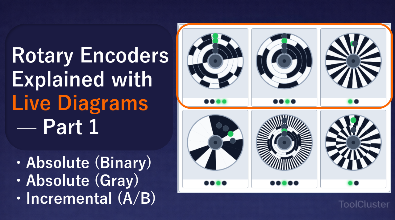
A rotary encoder turns the angle of a spinning shaft into an electrical signal. At the heart of one sits a disc marked with a pattern of light and dark, and a sensor that reads that pattern from a fixed position. Change how the pattern is cut, and you change both what the encoder can tell you and how it fails when a reading goes wrong.
This series walks through those patterns one style at a time, using diagrams you can spin. This page covers the multitrack absolute designs, where each track carries exactly one bit, in both binary and Gray code, along with the classic incremental disc that carries no absolute address at all.
Designs that squeeze position data onto a single track, such as the PRBS disc, and designs that pair a coarse code with a fine cycle, such as hybrid and vernier discs, are covered in (2) Single track and hybrid.
| Question | Figure that answers it |
|---|---|
| Why does the angle come out right the instant the power goes on? | Absolute encoders with binary code (Figure 1) |
| Why has Gray code become the default on industrial discs? | Absolute encoders with Gray code (Figure 2) |
| How does a disc with no absolute address work out which way it is turning? | Incremental encoders with A and B channels (Figure 3) |
Every disc below can be dragged. Nudging one across a sector boundary before you read the text makes the rest of the explanation much easier to follow.
One thing to establish up front: each figure is a simplified drawing made to explain a mechanism, not a copy of any particular manufacturer’s product. Wherever the drawing departs from real hardware, the section headed “In the figure on this page” says so.
Absolute encoders with binary code (Figure 1)
How the encoding works
The disc is divided radially into concentric tracks, and each track carries one bit. At any given angle, the combination of light and dark across those tracks is the absolute address of that position. Cut the pattern in plain binary and four tracks give you sixteen addressable sectors; eight tracks give you 256.
The appeal of this arrangement is that position is known the instant the power comes on. Nothing has to move first. Whatever combination the sensors happen to be reading is already the angle, so there is no homing routine at start-up.
The weakness comes from the same mechanism. At the boundary between two addresses, several bits can flip at the same moment. Going from 0111 to 1000, for instance, changes all four bits at once. If the sensors are mounted even slightly out of line, each bit crosses its edge at a marginally different time, and for a brief moment the reading is neither 0111 nor 1000. Worse, the error is not small: a momentary misread can land half a revolution away from the true position.
In the figure on this page
The drawing follows the intuition of a transmissive absolute encoder, so white means 1 (light passes) and black means 0 (light is blocked). The tracks run LSB on the outside, MSB on the inside. A fixed row of sensors at the top of the disc reads each track, and the lamps below the disc line up with them: leftmost is the MSB on the inner track, rightmost the LSB on the outer one.
Moving the slider changes the bit count, and with it the number of tracks and the number of sectors. The disc is set up so that turning clockwise makes the sector number count up. Walk it slowly across a boundary and watch for the moment when more than one lamp changes at once.

More bits does mean finer resolution, but it also means more bits changing together at the worst boundaries. Raising the sector count while staying in plain binary makes the occasional misread jump further, not less far.
Absolute encoders with Gray code (Figure 2)
How the encoding works
Physically nothing changes: one track per bit, exactly as before. What changes is the code cut into those tracks. The sectors are ordered so that any two neighboring angles differ by exactly one bit. That ordering is Gray code.
Because only one bit can be in transition at a boundary, a badly timed reading can only ever return the sector you are leaving or the one you are entering. Errors stay next door instead of flying across the disc, and that single property is why Gray code became the default for industrial multitrack encoders.
The catch is that a Gray reading is not a number you can use directly. The controller or PLC has to convert it to plain binary before doing any arithmetic with it. Treat the conversion step as part of the design rather than an afterthought.
In the figure on this page
The physical layout matches Figure 1 exactly — LSB outside, MSB inside, white for 1, black for 0 — but each sector now carries its Gray pattern. Turn the disc clockwise and the sector number still counts up one at a time.
The Gray value in the readout is a different story. Read the bit pattern on the disc as a decimal number and it goes 0, 1, 3, 2, 6 and so on, skipping around instead of climbing. The plain binary equivalent is shown alongside it, so you can watch the sector number and the converted value stay in step while the raw Gray value jumps.
Watch the lamps too. Crossing into an adjacent sector generally flips exactly one of them. Set against the binary disc in Figure 1, where several changed together, the difference is easy to see.

A readout that goes 0, 1, 3, 2 is not a sign of a faulty disc. On a Gray encoder that is exactly what you should see. The values that climb one at a time are the converted ones.
Incremental encoders with A and B channels (Figure 3)
How the encoding works
An incremental disc carries nothing but evenly spaced slits around its circumference, and no absolute address whatsoever. It is read with two sensors placed roughly 90 electrical degrees apart, in quadrature. By convention the two are called channel A and channel B.
Together the pair cycles through four states, normally 00 → 10 → 11 → 01, or the same sequence in reverse when the shaft turns the other way. The part people tend to miss is that there are stretches where A and B are both high, and stretches where both are low. The two channels are not simply inverted copies of each other taking turns.
Which channel leads tells you the direction of travel, and counting edges tells you how far the shaft has moved. That is also the limit of what an incremental encoder knows. It only ever reports change. Lose power, or drop a count to noise, and the absolute position stays unknown until a reference mark such as a Z channel comes round again.
In the figure on this page
There is a single code track carrying evenly spaced slits. Channel A sits at the top of the disc and channel B is offset by the equivalent of 90 electrical degrees.
You will see moments where both lamps are lit and moments where both are dark. Those are the overlap points inherent to quadrature, and they are correct. The resolution slider acts as the number of divisions, equivalent to PPR (pulses per revolution). There are only two lamps, A and B, with no MSB or LSB row.

Seeing A and B lit at the same time gets diagnosed as a wiring fault surprisingly often. In quadrature, two of the four states have both channels matching, so this is normal. What should worry you is the opposite: a signal where either 00 or 11 never appears at all.
Where each of the three types actually turns up
The differences above map fairly directly onto where each type gets used. What follows describes general tendencies; which type sits inside any particular unit varies by model, so check the datasheet when you are specifying real hardware.
Binary absolute encoders
Discs cut in plain binary are rare in practical rotation sensing. The flaw of multiple bits changing together at a boundary translates too readily into misbehavior downstream. Where a multitrack disc needs to carry absolute position, it has almost always been replaced by the Gray version described next.
That does not mean binary disappears. The value read off a Gray disc is converted to plain binary in the controller before any position arithmetic happens. Binary has retreated as a way of cutting the disc while remaining the basis for the calculation.
Gray code absolute encoders
This is the standard choice for industrial multitrack discs. Its strength, as covered above, is that the angle is settled the moment power arrives. That matters most where driving the machine around to find a home position at every start-up is not acceptable.
Typical applications include indexing axes on machine tools, robot joint angles, valve and damper openings, hoist and crane positions, and the bearing of antennas and observation instruments. In each case, either not knowing the current position after a power cut would be dangerous, or homing the mechanism is physically awkward in the first place.
Once those encodings have given you the joint angles on a robot, the next questions are where the tool is now, and how far to rotate each axis to get there. That calculation is in Forward and Inverse Kinematics Explained with Live Diagrams (1), on a planar 2-link arm you can move.
Incremental encoders (A/B)
This is the simplest construction of the three and needs only one code track. Giving up absolute position buys you a cheap way to follow rotation finely.
Speed and direction feedback from motors, belt travel on conveyors, paper feed in printers and scanners, adjustment knobs on control panels, and the scroll wheel on a mouse all live here. What they share is either the freedom to re-establish a reference at start-up, or no need for absolute position to begin with.
Rather than choosing by the name of the type, settle one question first: does the machine need to know where it is the moment it is switched back on? If it does, you want an absolute encoder. If it does not, incremental will do.
What each of the three types prioritizes
All three read a pattern off a disc, but they part company over what they treat as most important.
| Type | Absolute position | Misreads at a boundary | Code tracks needed |
|---|---|---|---|
| Binary | Known as soon as power is applied | Can land a long way off | One per bit |
| Gray | Known as soon as power is applied | Never worse than the next sector | One per bit |
| Incremental | Unknown until a reference is found | Not applicable (relative only) | One |
So: absolute position calls for a multitrack absolute disc, and keeping boundary errors small within that calls for Gray. Incremental gets by with a single track and a much simpler disc, but absolute position then has to come from somewhere else.
Which raises the obvious question — can a disc carry absolute position without adding tracks? That line of thinking leads to the single-track PRBS disc, which writes a pseudo-random sequence around one ring, and to hybrid discs that pair a coarse code with a fine cycle. Those are the subject of (2) Single track and hybrid.
Frequently asked questions
Q1. Should I choose an absolute or an incremental encoder?
A. The first fork in the road is whether you can tolerate a homing move after every power-up. If you can, incremental is fine; if you cannot, you need absolute. The real decision also depends on the safety requirements of the machine and the capabilities of the control system, so this article stops at the difference between the types.
Q2. My Gray readout goes 0, 1, 3, 2. Is the disc faulty?
A. No. Gray code is arranged so that neighboring angles differ by a single bit, which means reading the bit pattern straight off as a decimal number produces an order that skips. As long as the converted plain-binary values run 0, 1, 2, 3, everything is working.
Q3. Is it abnormal for channels A and B to be high at the same time?
A. It is normal. Reading in quadrature means cycling through 00, 10, 11 and 01, so there will always be a stretch with both channels high and a stretch with both low. Two channels that are permanently opposite would mean a 180 degree phase difference, and that arrangement cannot tell you which way the shaft is turning.
Q4. Does adding bits improve accuracy in proportion?
A. It increases the number of divisions, but every extra bit adds another track and makes the pattern near the rim finer. Push the bit slider up in the figures and you can see how quickly the outermost track tightens. On real hardware that fineness runs into the limits of manufacturing tolerance and sensor resolution.
Q5. Do these figures match a real product?
A. They do not. They are simplified drawings meant to show a mechanism. Track order, the assignment of light and dark, and sensor placement were all chosen to make the explanation clear, and real hardware may add a synchronization track or several read heads. Each section’s “In the figure on this page” sets out what is specific to the drawing.
Leave a Reply