Walk through a factory today and you will find that equipment without a network connection is the exception. Managing the assigned IP addresses is becoming part of routine work. Yet when the conversation turns to the trailing /24, plenty of people suddenly lose confidence. And when an instruction like “we’re adding cameras, so split it at /25” lands out of nowhere, confusion is common.
This article explains how to read the slash in an IP address as the dividing line of an equipment LAN. That scheme is called CIDR, and the position of the dividing line decides how many host addresses the network can hold. What belongs on the same network, and whether a switch alone can still deliver after a split — these are becoming basic networking tasks, and this article walks through them. It continues from switches and routers in the equipment LAN.
Key points of this article
| What to look up | Key point |
|---|---|
/24 and cable count | The first 24 of 32 bits are the network side. 256 addresses — not the number of cables |
/24 and /25 address counts | Half the hosts: 256 → 128 → 64 |
| Mask and CIDR | 255.255.255.0 and /24 are two ways to write the same dividing line |
Broadcasts on the same /24 | On the same /24, broadcast traffic reaches the PLC too |
| Subnet splits and switches | A switch alone cannot cross into another subnet; a router is needed at the boundary |
| Sizing from device count | Derive the prefix length from the addresses you need. Splitting at varied lengths is the tool’s job |
| Longest prefix match | Where routes overlap, the row with the longer match stays |
| Checks on the floor | Nameplate IP and mask, your current IP, the Calculator tab |
/24 and cable count
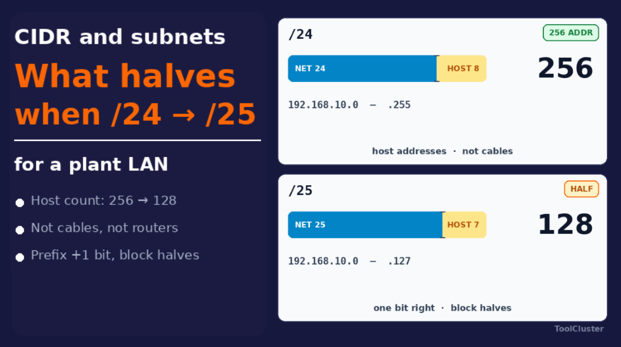
An IPv4 address — the kind used throughout industrial equipment today — is a 32-bit number. The /24 in CIDR marks a dividing line across those 32 bits: the first 24 belong to the network side (the network part), the remaining 8 to the device side (the host part). With 8 host bits there are 28 = 256 addresses. In 192.168.10.0/24, everything from 192.168.10.0 to 192.168.10.255 is one network.
The common mix-up on the floor is reading that 256 as a port count or a cable count. Your switch may have 8 ports, and only 3 devices may actually be plugged in — if the address plan says /24, the network still has 256 addresses. Adding another switch gives you more ports, not one extra address. The number of sockets on a box and the range an IP address covers are two different things.
The larger the number after the slash, the longer the network side and the fewer addresses left for devices. /16 is wide. /30 fits two devices facing each other. Remember it that way, and the first thing you will read off any address table is how many devices the network can hold.
/24 and /25 address counts
Increase the number after the slash by one, and the network side grows by one bit while the device side shrinks by one. That number is called the prefix length. Each step halves the address count: /24 gives 256, /25 gives 128, /26 gives 64. The figure below shows the boundary moving one cell to the right — and the available hosts halving each time.
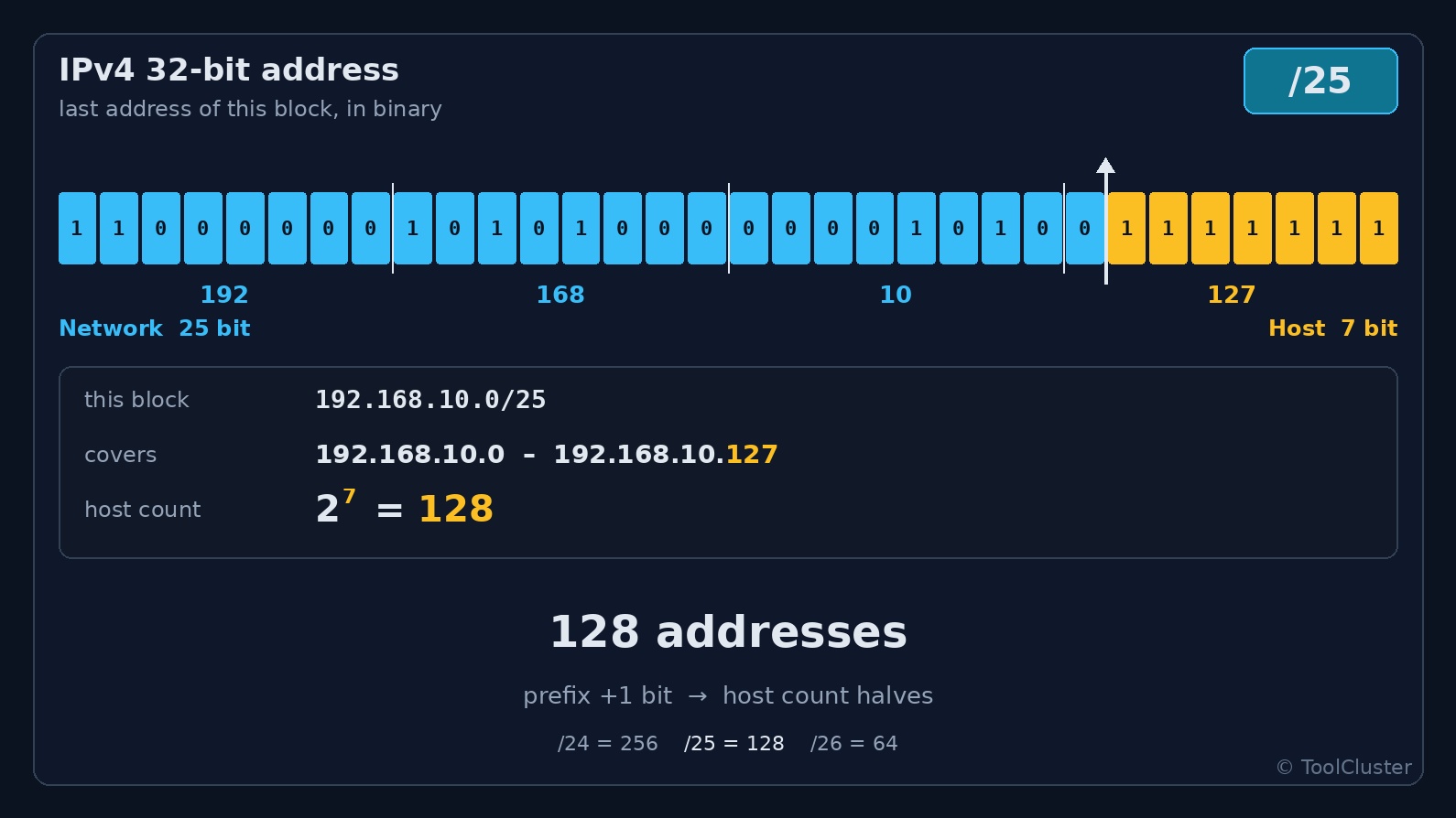
In the figure, the boundary sits at /25, giving 128 addresses. Of any 256, the first and last are usually reserved — one for the network itself, one for the everyone-at-once address (broadcast) — which is why some sites count usable hosts as 254 versus 126. But the answer to “what is halved when /24 becomes /25” is not about those reservations. It is the size of the block: 256 down to 128. Neither your cables nor your routers are cut in half.
The instruction from the opening — “split it at /25” — means splitting 192.168.10.0/24 into 192.168.10.0/25 (.0–.127) and 192.168.10.128/25 (.128–.255). To move the bits on your own table, the Visualizer tab of the CIDR tool shows the same dividing line in color as this figure.
Mask and CIDR
On equipment screens you will more often see something like 255.255.255.0 than a slash. That is the subnet mask: the first 24 bits set to 1, the rest to 0 — the same dividing line as CIDR’s /24. They are not different things; there are simply two notations for one cut. For /25, the mask is 255.255.255.128.
Nameplates and PLC setup screens tend to use mask notation, while design documents and cloud consoles tend to use CIDR. Whichever appears, you are looking at the same dividing line. The /24 that came up in why office networks get slow is this same cut.
Changing only the address to the neighboring network’s numbering while the mask stays at /24. If the exit to other networks (the gateway) is also left on the old network, the link light comes on but nothing arrives over IP. Whenever you touch the numbers, check address, mask, and gateway as a set.
Broadcasts on the same /24
What happens if the camera from the opening is added to the same /24 as the PLC? Being on the same /24 is almost the same as being inside the range where signals sent to no particular destination reach everyone (the broadcast domain). When the camera sends its who-is-there signal (ARP) and starts pushing out chunks of video, that traffic reaches the PLC, the operator screens, and the I/O stations away from the cabinet — everything on that network. A switch does not look at IP, so it will not decide “this is control traffic, keep the rest out” for you.
It works at first. The trouble is that a week or so after PCs and cameras are added, the occasional delays begin. The failure pattern is the same as a slow office network: the broadcast domain is too wide. To protect cyclic communication, move the cameras to a different cut and stop them at the boundary.
Subnet splits and switches
Now suppose you follow the instruction and split the /24 into two /25s. With the PLC at 192.168.10.10 and a line PC at 192.168.10.200, the addresses look like neighbors. But under a /25 mask they are separate networks, even if both cables plug into the same switch. A switch is a box that forwards only within one dividing line, so it will not cross this boundary.
To deliver across it, you need a box at the boundary that reads the IP and rebuilds each bundle of data for the next network: a router, or a switch with routing built in (an L3 switch). This is exactly the line between switches and routers. Cutting a network and forwarding between the pieces are separate jobs. And deciding whether traffic may pass beyond the boundary at all is the job of the firewall.
Sizing from device count
How do you choose the length of the cut? Rather than laying down a /24 first and discarding the leftovers, it pays to start from the number of addresses you need and derive the number after the slash. For 60 hosts, a /26 (64 addresses) is often enough — there is no need to hand a whole /24 to the neighboring line. Count not just today’s devices but next year’s additions and the maintenance laptops that get plugged in. Whether you then allow for the two reserved addresses and go one size up is a judgment call for your site.
When each line needs a different number of devices, do not cut everything to the same length — vary the length to match the demand. That approach has a name, VLSM, but the name matters less than the order of thinking: device count first, then length. This article does not cover the procedure itself. Hand the parent network and the per-line device counts to the Split / VLSM tab of the CIDR tool.
Longest prefix match
Once several cut networks exist, the router has to choose which dividing line a destination falls into. With 10.0.0.0/8, 10.10.0.0/16, and 10.10.20.0/24 in the table, the destination 10.10.20.45 matches all three. The winner is the row with the most matching bits. This is called the longest prefix match. Shorter prefixes mean wider networks; longer ones are more specific. The figure below shows how the choice plays out.
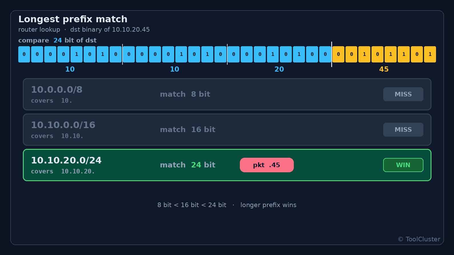
In the figure, the destination sits on the /24 row, with /8 and /16 out of the running. On the plant floor, too, the longer cut is the one that stays. The catch-all escape route (0.0.0.0/0) is the shortest cut of all, so if a /24 for the line exists, the /24 wins — the same rule at work. The logic is identical in allow lists and cloud routing tables. To see which row your own list would hit, use the Compare tab of the CIDR tool.
Checks on the floor
Now take these dividing lines to your own equipment. On the nameplate or the setup screen, read three things together: the IP, the mask (or CIDR), and the exit to other networks. Whether two devices share a network is decided not by how similar the addresses look but by whether the dividing line is the same. Even .10 and .200 are one network under /24 — and two networks under /25.
To see which address your laptop holds right now, use the IP address check. For recalculating the CIDR in a design document, or converting between mask and slash, use the Calculator tab of the CIDR tool. The division of labor: the Visualizer tab for the bit boundary, the Split / VLSM tab for sizing from device counts, and the Compare tab for route matching.
Summary
What is halved when /24 becomes /25 is the number of host addresses. Cables and switch ports are not. Written as masks, the same dividing lines read 255.255.255.0 and 255.255.255.128. Add cameras to the same network and broadcast traffic mixes in; split the network and a switch alone no longer reaches the neighbor.
The bit boundary, sizing from device counts, and route matching can all be replayed with your own table in the CIDR visualizer. The box side of the work — forwarding within one network versus rebuilding at the boundary — lives in the equipment LAN article, and the standards themselves in the industrial communication article.
Frequently asked questions
Q1. What exactly is halved when /24 becomes /25?
A. The number of host addresses: 256 becomes 128. Not the number of cables or switches. Counting usable hosts as 254 versus 126 comes after removing the network’s own address and the everyone-at-once address.
Q2. Are the subnet mask and CIDR different things?
A. The dividing line is the same. A mask writes the bits as a run of 255s; CIDR writes how many leading bits there are, as /24. 255.255.255.0 is /24, and 255.255.255.128 is /25.
Q3. Can the PLC and the operator screen share the same /24?
A. Devices that talk to each other on the same cycle usually do share a network. But once cameras and office PCs join the same /24, broadcast traffic enters the control side. Keep only the devices that must hold the cycle on the same dividing line.
Q4. Does splitting a /24 in two require a router?
A. Yes, if the separated networks are to talk over IP. A switch forwards only within one dividing line and does not cross the boundary. A switch with routing built in (an L3 switch) is doing that same job at the boundary.
Q5. What is longest prefix match?
A. When a destination fits several routes, the row with the most matching bits is the one used. For 10.10.20.45, given /8, /16, and /24, the /24 remains.
Q6. Does the same thinking apply to IPv6?
A. Reading the dividing line works the same way; what differs is the customary numbers. A site allocation is often a /48, a single network a /64. The body of this article covers IPv4 equipment LANs. IPv6 calculations are available in the CIDR tool.
Q7. How do this article’s figures differ from the CIDR tool?
A. The figures cover just two points: addresses halving from /24 to /25, and the longer prefix winning. Calculations on your own address table, sizing from device counts, and checking a route list belong to the tool’s Calculator, Visualizer, Split / VLSM, and Compare tabs.
Leave a Reply