This article uses Python and OpenCV to run a perspective transform: move an image’s four corners onto four new ones. In outline, getPerspectiveTransform builds the matrix and warpPerspective warps the pixels. The example is a 600×600 grid with a person silhouette.
Key points
| Look at this | Point |
|---|---|
| What we are doing | Set where the four corners go, and the plane stretches into a trapezoid |
| Code and result | Run the script below with the same folder layout as the figure |
| Folders | Put source_pics and save_pics next to the script |
| Coordinates | Top-left is [0, 0]. Order is top-left → bottom-left → bottom-right → top-right |
| The remaining lines | Read, size, matrix, warp, save |
| Output size | Pixels outside the third argument are cropped |
| Your own image | Change only the point order and the output size to the rectangle you want |
| A constrained camera | Even from an angle, matching the four corners of the real plane still yields a rectangle of data |
A perspective transform sets where the four corners go
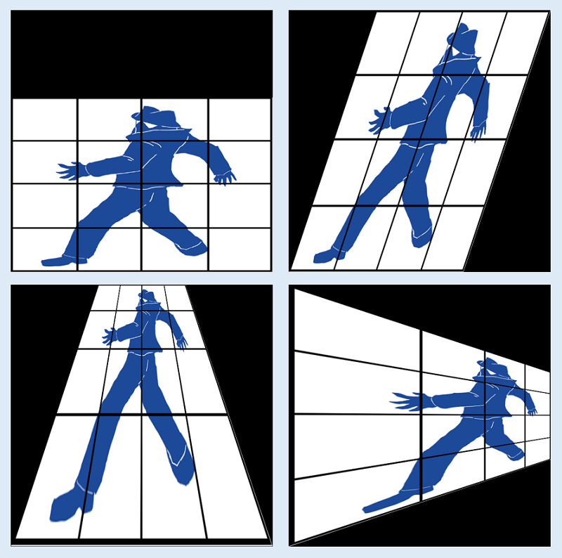
An affine transform (warpAffine) keeps parallel lines parallel. A perspective transform (getPerspectiveTransform and warpPerspective) can move the four corners independently, so you can make a trapezoid that is wide in front and narrow in the back. Flattening a business card to a rectangle, or looking down on a floor, belong to these functions.
Pass the input corners and the output corners in the same order. This article does not walk through the algebra inside the matrix. If you know where the four corners go, you can use the functions.
The script and before/after
A working script first. The next sections follow the coordinates and the remaining lines.
import numpy as np
import cv2

image = cv2.imread("source_pics/test_1.png", cv2.IMREAD_COLOR)

height, width, channels = image.shape[:3]

source_points = np.array([[0, 0], [0, height], [width, height], [width, 0]], dtype=np.float32)
target_points = np.array([[200, 0], [0, 600], [600, 600], [400, 0]], dtype=np.float32)

mat = cv2.getPerspectiveTransform(source_points, target_points)

perspective_image = cv2.warpPerspective(image, mat, (width, height))
cv2.imwrite("save_pics/perspective_image.png", perspective_image)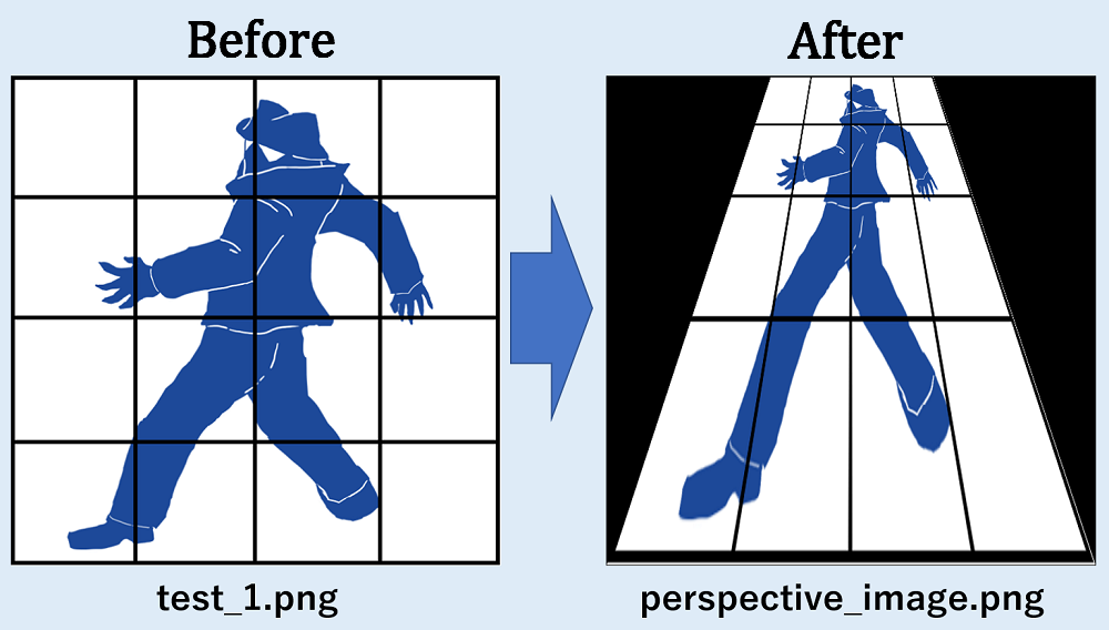
This example pulls the top edge inward, so the result is a trapezoid that is narrow at the top and wide at the bottom. The black margin is the part of the output canvas that sits outside the warped quad.
Put the folders next to the script
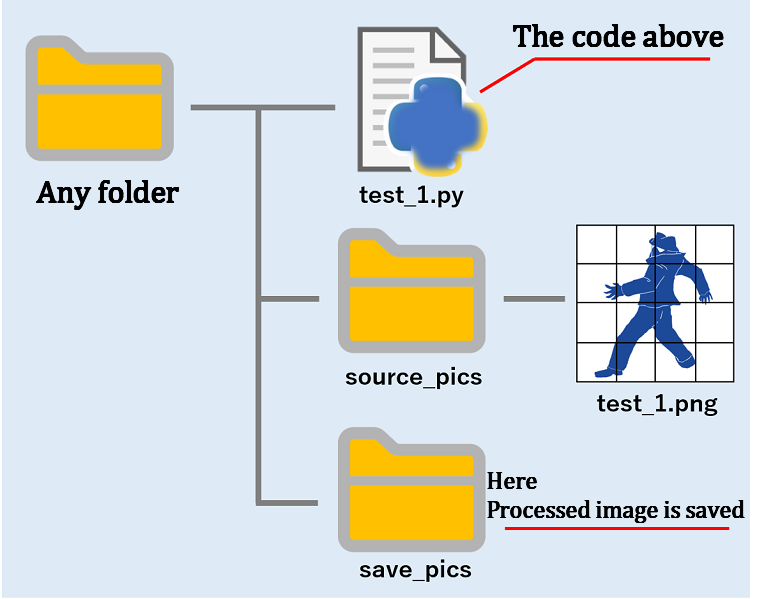
Paths in the code are relative to the test_1.py you run. The image you read is source_pics/test_1.png; the file you write is save_pics/perspective_image.png. For your own files, match those names or change the path strings.
If imread fails, image is None and the next line, image.shape, stops. Before you run, check the folder spelling and the current working directory.
Coordinates start at [0, 0] in the top-left
source_points = np.array([[0, 0], [0, height], [width, height], [width, 0]], dtype=np.float32)
target_points = np.array([[200, 0], [0, 600], [600, 600], [400, 0]], dtype=np.float32)
The arrays are in this order. The origin is not at the bottom, as on graph paper.
| Order | source_points | target_points |
|---|---|---|
| Top-left | [0, 0] | [200, 0] |
| Bottom-left | [0, height] | [0, 600] |
| Bottom-right | [width, height] | [600, 600] |
| Top-right | [width, 0] | [400, 0] |
This example is 600×600, so height and width are both 600. Filled in, the arrays look like this.
source_points = np.array([[0, 0], [0, 600], [600, 600], [600, 0]], dtype=np.float32)
target_points = np.array([[200, 0], [0, 600], [600, 600], [400, 0]], dtype=np.float32)![A four-corner map for a perspective transform, referenced to source_points and target_points. It shows that with origin at the top-left, pulling the top edge in shortens the top. [0, 0] and [600, 0] move to [200, 0] and [400, 0].](https://toolcluster.app/wp-content/uploads/2026/08/opencv-perspective-coords.png)
The two top points move inward, so the top edge gets shorter. The two bottom points stay put. Change the numbers and the same four-corner pairing makes a different trapezoid.
If the input order and the output order do not match, the mapping twists. Write both as top-left → bottom-left → bottom-right → top-right. If you pick points on a mathematical y-axis (up is positive), the image looks upside down.
What the remaining lines do
Imports
import numpy as np
import cv2
NumPy holds the point arrays. OpenCV’s cv2 reads, writes, and warps images.
Reading the image
image = cv2.imread("source_pics/test_1.png", cv2.IMREAD_COLOR)cv2.imread loads test_1.png from source_pics, next to the script, in colour, into image.
Image size
height, width, channels = image.shape[:3]shape gives height, width, and channel count. This example does not use the channels, but the number of values you unpack has to match, so all three are taken.
Match the number of variables to the number of values you unpack.
Points for the matrix
source_points = np.array([[0, 0], [0, height], [width, height], [width, 0]], dtype=np.float32)
target_points = np.array([[200, 0], [0, 600], [600, 600], [400, 0]], dtype=np.float32)
Four XY points each. On this source image [height, width] is [600, 600], so the arrays contain:
source_points =  [[  0.   0.]
 [  0. 600.]
 [600. 600.]
 [600.   0.]]
target_points =  [[200.   0.]
 [  0. 600.]
 [600. 600.]
 [400.   0.]]
Those are the coordinates from the figure. The warp uses that pairing.
The transform matrix
mat = cv2.getPerspectiveTransform(source_points, target_points)cv2.getPerspectiveTransform computes the matrix from the four input corners and the four output corners. In this example the values are:
mat =  [[ 3.33333333e-01 -3.33333333e-01  2.00000000e+02]
 [ 0.00000000e+00  3.33333333e-01  0.00000000e+00]
 [ 0.00000000e+00 -1.11111111e-03  1.00000000e+00]]
You do not need the meaning of each entry here. If the corners go where you intended, pass the return value to the next line.
The warp
perspective_image = cv2.warpPerspective(image, mat, (width, height))cv2.warpPerspective takes the source image, the matrix, and the output width and height. This example only shortens an edge, so the output size stays (width, height), the same as the source. Pick the real size by looking at the transformed coordinates.
Saving
cv2.imwrite("save_pics/perspective_image.png", perspective_image)cv2.imwrite writes perspective_image.png into save_pics, next to the script. Create the folder first; the write fails if it is missing.
If the output is too small, the overflow is cropped
Keep the output at 600×600 and take points like these, and the stretched top leaves the canvas.
source_points = np.array([[200, 0], [0, 600], [600, 600], [400, 0]], dtype=np.float32)
target_points = np.array([[0, 0], [0, 600], [600, 600], [600, 0]], dtype=np.float32)![A crop when the output canvas is too small, shown by points that leave the frame. It explains that warpPerspective's third argument is the written image size. The original [0, 0] and [600, 0] sit outside 600×600, so the top is cut.](https://toolcluster.app/wp-content/uploads/2026/08/opencv-perspective-output-crop-en.png)
The third argument is the size of the image you write, not the size of the warped world. Pixels whose points sit outside that rectangle are gone. To keep them, enlarge the output first, or pick target points that all fit.
If a target x or y is past the output width or height, and you leave the third argument at the source size, you get a crop. When it looks cut, compare the points with the output size first.
The same steps work on your own photos
Keep the four-corner order and the same two functions work on photos that are not a grid. Change only the target numbers and the output size to the rectangle you want.
Even if the camera sits at an angle, matching four corners still gives you a rectangle
What you did is a short chain: pair the input corners with the output corners, solve for the matrix, and write onto the output canvas. The functions are the same on the grid and on a photo from the floor. On site, only how you pick the points and the output size change.
When the camera position is fixed by the machine
On equipment and inspection rigs, you often cannot put the camera directly above the part. Covers, pipes, guards, and robot reach are decided first; the lens is squeezed in afterwards. Measure or read that image as-is and you still have a trapezoid that is wide in front and narrow in the back, so lengths and positions are skewed.
Pair the four corners and you can recover the rectangle of the plane you want, without rebuilding the frame. Data collection still works when the camera pose is constrained by the structure. The real trick is to put the points on the four corners of the physical plane, not the four corners of the screen. A workpiece corner, a fixture hole, a floor joint — any point you can point to again later — and this article’s steps apply as written.
You do not have to write the maths yourself
OpenCV is one implementation for that job. Laying the points out with NumPy and handing them to OpenCV’s getPerspectiveTransform and warpPerspective is the choice to use a maintained implementation instead of writing the algebra yourself. That choice is not limited to OpenCV. Around image processing, numerics, comms, and control, the same work already has implementations, and people keep them and bump the versions. Reading and using that code gets you back to the machine’s constraints sooner than deriving the projective maths from scratch.
Using it is enough. If you hit a hole or something unclear, you can report it, fix the docs, or send a patch. How much you give back varies. Even zero still puts you on the side that keeps that work going, by waiting for the next release. Fit the tool to your machine, and give a little back if you need to. That loop spends engineering time better than owning a full in-house rewrite.
Even with a camera at an angle, four corners still make a rectangle of data. After that, the real job is to measure, read, and keep what sits on that rectangle.
Leave a Reply