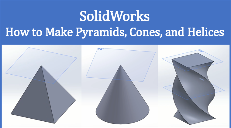
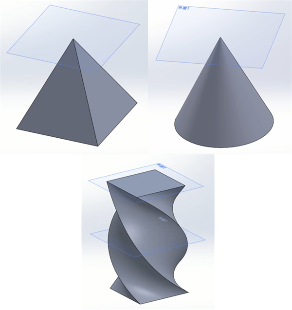
Loft a base sketch to a point on a height plane and you get a pyramid or a cone. In outline, you offset a plane, place the vertex, then pick the profiles in order. The second half uses three planes and a rotating click order to make a twisted column. (The screenshots are SOLIDWORKS Premium 2017, with English labels on the steps.)
Key points
| Look at this | Point |
|---|---|
| What we are doing | Loft a point on an offset plane to the base outline |
| Base | Sketch a square (or a circle) on Top. Example: 100 mm square, origin-centred |
| Height plane | Reference Geometry → Plane, offset by the height |
| Vertex | Sketch a point on the new plane and exit |
| Loft | Open Loft with nothing selected; click the base edge, then the point |
| Twisted column | Three planes; click corners in rotating order |
Screenshots show SOLIDWORKS®. Trademark notes are in the note at the end.
Loft a point on a reference plane to the base
Front, Top, and Right are not enough for a pyramid tip. Offset a reference plane by the height, sketch a point there, and Loft fills the faces from that point to the base outline. A square base gives a pyramid; a circle gives a cone. Extruded Boss/Base will not collapse a section down to a point.
Sheet-metal bends are a different workflow. The L-shaped part is in L-bend sheet metal.
Sketch the base on Top
Open a new part and start a sketch on Top. Centre a square on the origin; the example is 100 mm. For a cone, draw a circle in the same place — the rest of the steps stay the same.
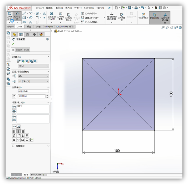
Sketch the base before extra planes appear, so you do not mix up which sketch sits where. Once Reference Geometry is familiar, you can add the planes first.
Add a height plane with Reference Geometry
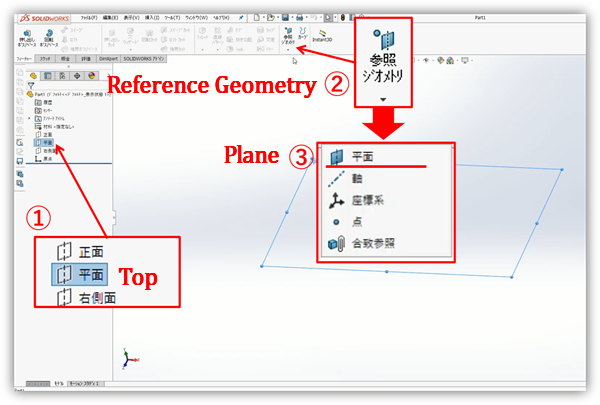
Exit the sketch. Select Top in the tree. On the Features tab, choose Reference Geometry, then Plane.
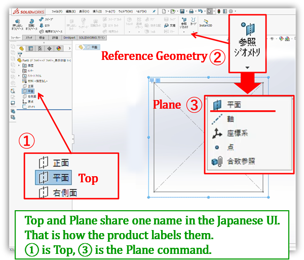
A preview plane appears. ① on the screenshot matches the table below.
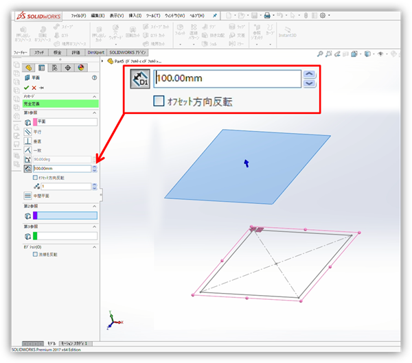
| No. | On the screenshot (Japanese UI) | What it sets | This example |
|---|---|---|---|
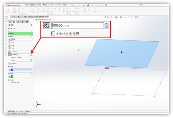
| ① | オフセット距離 | Offset distance — height of the new plane | 100 mm |
If the direction is wrong, turn on Flip offset. OK adds Plane1 to the tree.
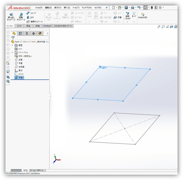
Sketch the vertex on the new plane
Select Plane1, start a sketch, and place the vertex. For a straight pyramid, that is directly above the centre of the base. Exit the sketch when the point is down.
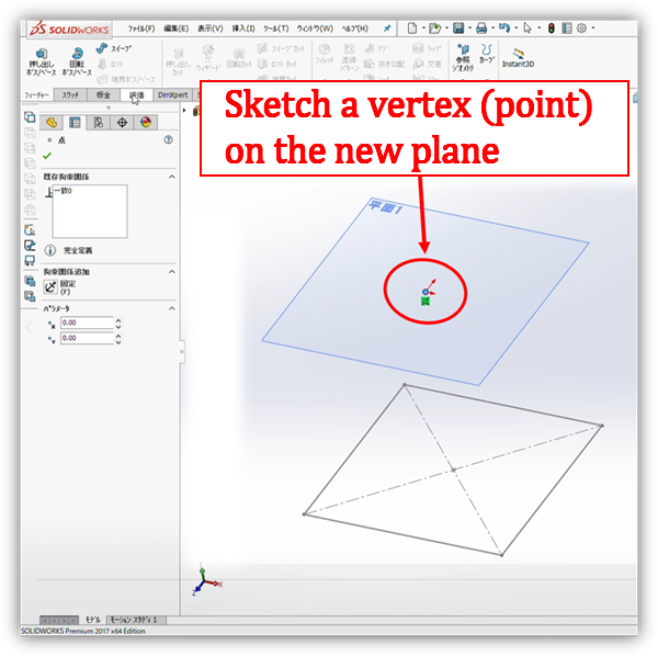
Loft the base to the vertex
Clear the tree selection, then open Loft on the Features tab.
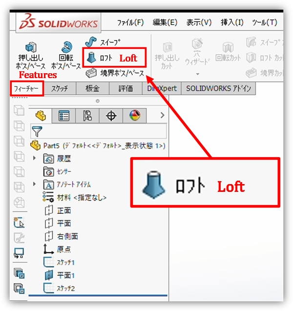
Starting Loft with a sketch or plane still selected. The Profiles list fills with the wrong items and the preview falls apart. Press Esc, click empty space in the graphics area, and open Loft again.
Pick the base edge and the point as profiles. Click 1 and Click 2 on the screenshot are that sequence.
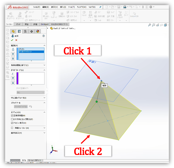
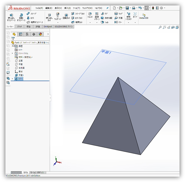
If the yellow preview is a pyramid, click OK. A circular base with the same clicks makes a cone.
For drawings or approval packs, the PDF toolkit can merge and rotate pages. That is about bundling for handoff, not CAD Save As.
Three planes and a rotating click order make a twisted column
Open a new part. If the offset is already clear, add one plane at half height and one at full height and skip the plane steps below. Those two, in order, are what follows.
With Top selected, open Reference Geometry → Plane. The offset is half the height you want. 100 mm here means a 200 mm finished height.
| No. | On the screenshot (Japanese UI) | What it sets | This example |
|---|---|---|---|
| ① | オフセット距離 | Height to the first new plane (half the finished height) | 100 mm |
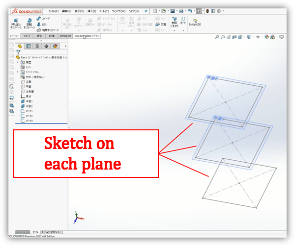
Select Plane1, run Reference Geometry → Plane again, and offset the same 100 mm. Counting the default plane, you now have three.
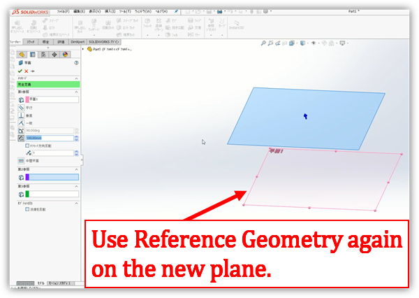
![Three stacked reference planes, shown as the default base plus two new levels. It explains the stations for the twisted-column profiles. Red labels mark [Default] base, [New] middle, and [New] top.](https://toolcluster.app/wp-content/uploads/2026/08/sw-helix-three-planes-en.png)
Sketch a 100 mm square on each of the three. Same size makes the twist easy to see.
Open Loft with nothing selected. Pick the bottom square, then the middle, then the top. Loft uses the nearest corner to the click. A straight stack stays a prism, so click one corner further around on each level.
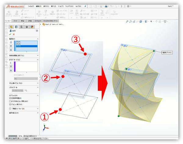
| No. | On the screenshot | What it does | This example |
|---|---|---|---|
| ① | Corner on the bottom square | First profile reference | Click the nearest corner |
| ② | Corner on the middle square | Second profile; offset from ① | An adjacent corner |
| ③ | Corner on the top square | Third profile; offset again | The next adjacent corner |
Clicking the same corner stacked on all three. The preview does not twist — you get a square prism. If the yellow highlight is straight, clear Profiles and pick again.
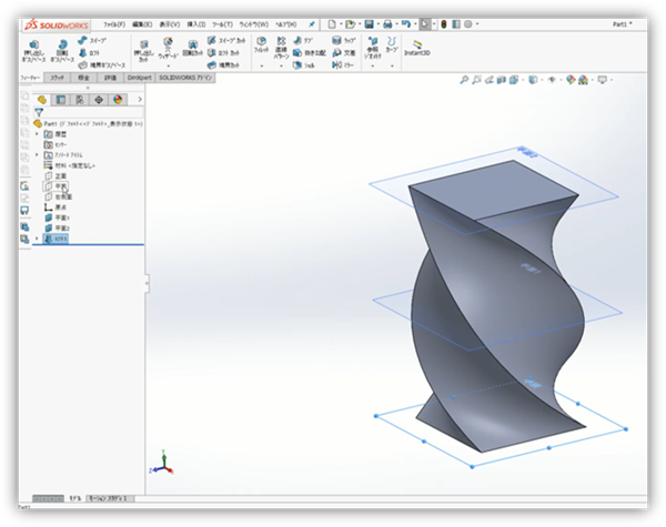
When the preview twists, click OK.
SOLIDWORKS® is a trademark or registered trademark of Dassault Systèmes or its subsidiaries. Screenshots on this page are for explaining how the product is operated. This site is not affiliated with or endorsed by Dassault Systèmes.
See Dassault Systèmes legal information for trademark handling.
Leave a Reply