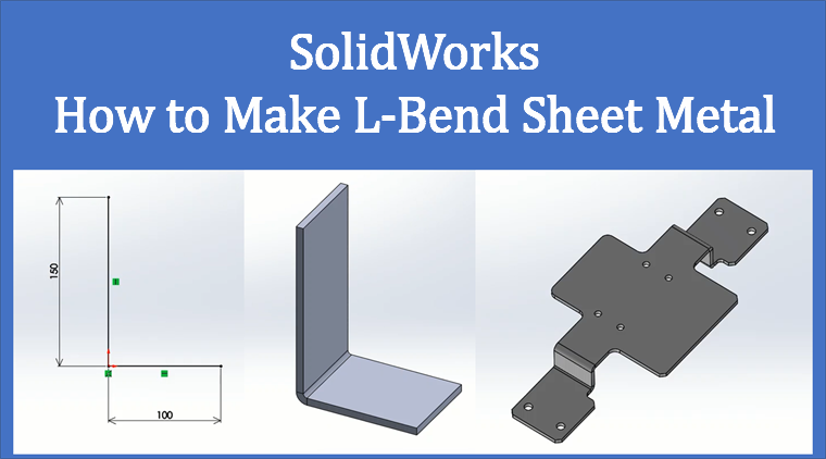
This article makes the simplest bent part — L-bend sheet metal — with SolidWorks Sheet Metal. In outline, you sketch an L-shaped profile, then set thickness, extrude depth, and bend radius in Base Flange/Tab to create the part. (The screenshots are the 2021 Japanese UI, with English labels on the steps. Check the command names on the version in front of you.)
Key points
| Look at this | Point |
|---|---|
| What we are doing | An L-shaped line becomes a solid with thickness |
| Profile sketch | Draw an L on Front, origin at the corner. Do not exit the sketch yet |
| Sheet Metal tab | If CommandManager has no Sheet Metal tab, right-click the tab row and turn it on |
| Base Flange | Hand the open sketch to a sheet-metal feature |
| Dimensions | The ones you usually touch are extrude depth, thickness, and bend radius |
| After you accept | Sketch on a face, cut holes, and keep going in the same part |
Screenshots show SOLIDWORKS®. Trademark notes are in the note at the end.
An L-bend starts as a line and becomes a solid
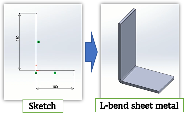
Covers and brackets use this shape all the time. Two flats joined at a single bend are already enough to practise bending. You can also stack two thin boxes with Extruded Boss/Base, but if you will need a flat pattern or to edit the bend radius later, starting with a Sheet Metal feature is less work downstream.
Here you draw the profile as lines, then give those lines thickness and depth. Those lengths are not the finished legs — half the thickness is consumed on the inside of the bend. The sketch section covers that relationship.
Sketch an L-shaped profile on the Front plane
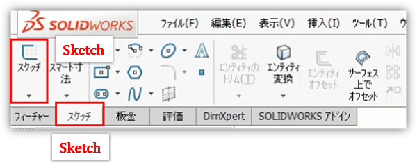
Open a new part. On the Features tab, choose Sketch, pick Front, and start the sketch.
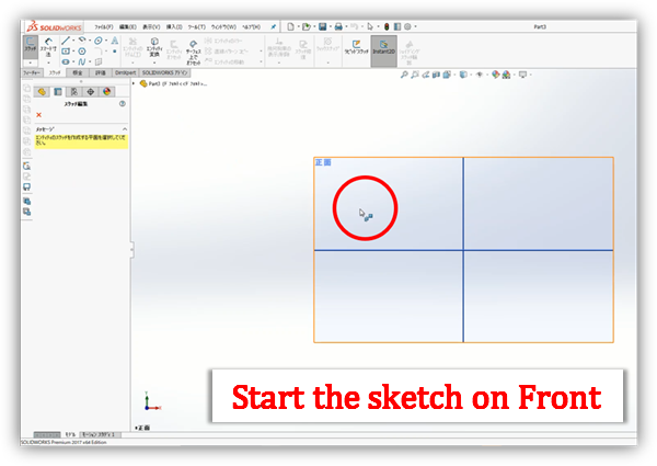
Put the origin at the corner and draw the L with lines. Do not exit the sketch yet. If you already did, select that sketch in the tree and Base Flange will still pick it up.
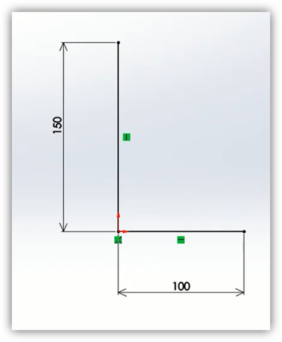
The example is 150 tall and 100 wide. You can change dimensions later. As a rule of thumb, a finished edge is about the line length plus half the thickness, because the inside bend radius rounds off the corner of the lines.
Check that vertical and horizontal relations are on. If you take a skewed L into Base Flange, the legs will not sit where you meant.
Show the Sheet Metal tab if it is missing
Skip this section if the Sheet Metal tab is already visible. If not, right-click the CommandManager tab row. Click Sheet Metal in the list so the tab stays on.
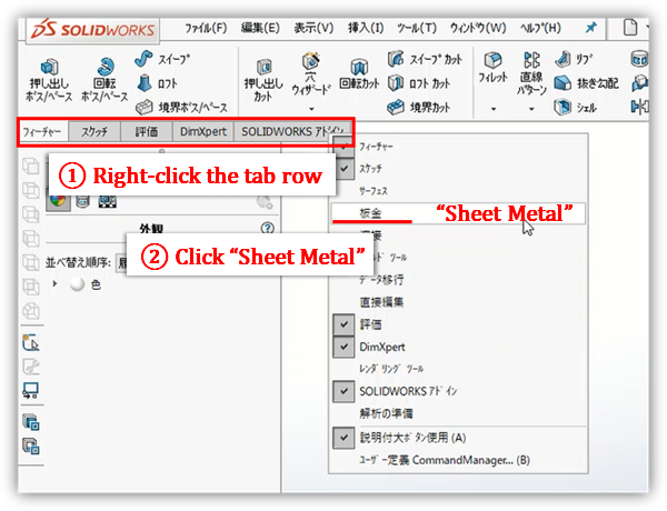
Some versions add spaces or a slightly different label. If the list has “Sheet Metal” or “板金”, that is the tab you want.
Turn the sketch into sheet metal with Base Flange
From the Sheet Metal tab, choose Base Flange/Tab. If you already exited the sketch, select it in the tree on the left, then run the same command.
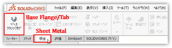
The L-bend preview highlights. Do not accept yet — set the values in the next section, then click OK.
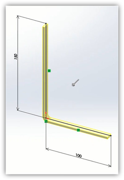
Running Base Flange after you exited the sketch, with neither a plane nor a sketch selected. The command starts, then stops because it has no profile. Click the sketch name in the tree, then Base Flange again.
Set extrude depth, thickness, and bend radius
Shape the part in the PropertyManager on the left. Numbers ①②③ on the screenshot match the table below.
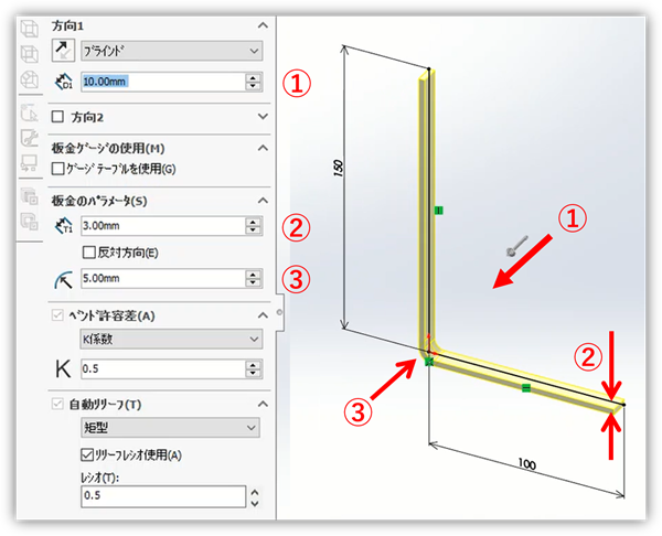
| No. | On the screenshot (Japanese UI) | What it sets | This example |
|---|---|---|---|
| ① | 方向1 / ブラインド | Extrude depth (Direction 1, Blind) | 10 mm |
| ② | 板金のパラメータ(厚さ) | Thickness | 3 mm |
| ③ | ベント半径 | Inside bend radius | 5 mm |
The example uses 10 mm extrude, 3 mm thickness, and 5 mm bend radius. K-Factor and auto relief can stay at the defaults for a first L-bend. Match the shop table later, when flat-pattern accuracy matters.
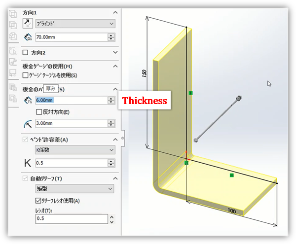
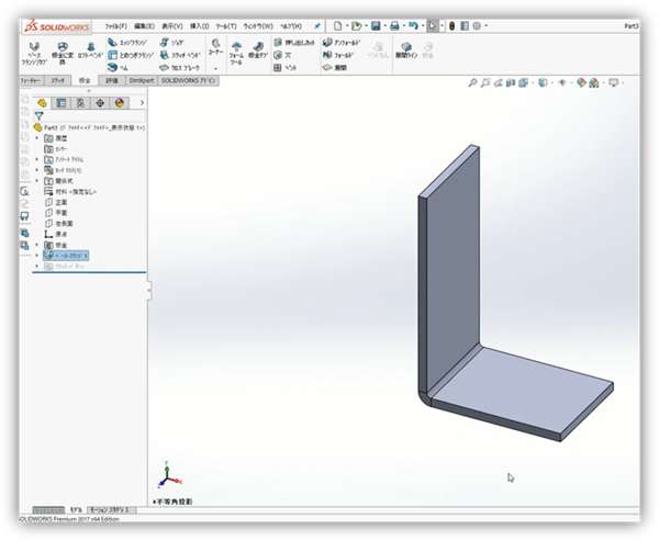
When the values are set, accept. A sheet-metal feature appears in the tree, and the preview colour becomes ordinary faces.
For drawings or approval packs, the PDF toolkit can merge and rotate pages. That is about bundling for handoff, not CAD Save As.
What you can do after you accept
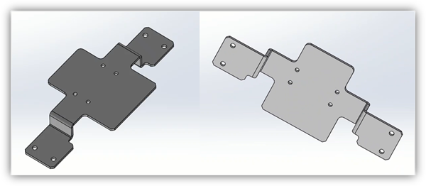
You can sketch on a face and cut holes. Add flanges and it starts to look like a cover. The way in is the same Sheet Metal tab.
Pyramids and helices — solids that are not sheet metal — move to this site in another article. This one is the smallest bending unit.
SOLIDWORKS® is a trademark or registered trademark of Dassault Systèmes or its subsidiaries. Screenshots on this page are for explaining how the product is operated. This site is not affiliated with or endorsed by Dassault Systèmes.
See Dassault Systèmes legal information for trademark handling.
Leave a Reply